
Sensor unit and motion analysis device

Inactive Publication Date: 2013-11-14
SEIKO EPSON CORP
View PDF8 Cites 48 Cited by
  • Summary
  • Abstract
  • Description
  • Claims
  • Application Information

AI Technical Summary

Benefits of technology

The invention is a motion analysis device that can accurately detect the motion of an object without being affected by the type of attachment used to connect the device. The device uses a piezoresistive pressure sensor that can be manufactured using semiconductor technology and is compact and accurate. The cutoff frequency of the high-frequency band can be adjusted based on the hardness of the attachment, reducing the influence of noise and improving the accuracy of motion detection. The device can be used in various sports activities to analyze and improve athletic skills by detecting accurate motion.

Problems solved by technology

However, when an object is a person, the person may be unwilling to bring the motion sensor into direct contact with the skin.
However, noise may be most absorbed or may not be absorbed by the attachment depending on hardness of the attachment.
Accordingly, even when a sensor unit which includes a motion sensor and a filter passing a prescribed frequency band is used, if the type of the attachment changes, it is difficult to detect an accurate motion of an object to be measured.
When the attachment is hard, high-frequency noise is likely to be transferred to the motion sensor.

Method used


Image

  • Sensor unit and motion analysis device
  • Sensor unit and motion analysis device
  • Sensor unit and motion analysis device

Examples


modification example

4. MODIFICATION EXAMPLE

[0075]In the foregoing embodiment, the pressure sensor 50 measures hardness of the attachment 80. However, for example, when the type of the attachment 80 is determined in advance, it is efficient to designate the type of the attachment 80 from the outside of the sensor unit 10. At this time, the pressure sensor 50 may not be included in the sensor unit 10, whereby manufacturing costs of the sensor unit 10 can be suppressed.

[0076]As shown in FIG. 9, a sensor unit 10 of this modification example includes an operating unit 60 which receives an instruction from the outside of the sensor unit 10 and generates an instruction signal, instead of the pressure sensor 50. The operating unit 60 outputs the instruction signal as a hardness signal 16. For example, it is assumed that the type of the attachment 80 is determined in advance into three types of (A) plate, (B) skin or felt, and (C) rug. A user who mounts the sensor unit 10 of this modification example on the obj...

application example

5. APPLICATION EXAMPLE

[0078]The sensor unit 10 of this embodiment can be suitably used in, for example, a motion analysis device. The motion analysis device is, for example, a device which analyzes swing of golf or tennis, batting of baseball, sliding of figure skating, running of running exercise, or the like, and uses the analysis to improve athletic skills.

[0079]For example, even when the sensor unit 10 which is part of the motion analysis device is attached to a figure skates through the hard attachment 80, the motion analysis device of this application example cuts high-frequency noise which occurs due to minute unevenness of the surface, thereby analyzing an accurate motion of an athlete.

[0080]For example, when the sensor unit 10 which is part of the motion analysis device is attached to a golf club or a tennis racket through the attachment 80 of sponge or the like, the motion analysis device of this application example also includes a motion of a low frequency to be transferr...


PUM


Abstract

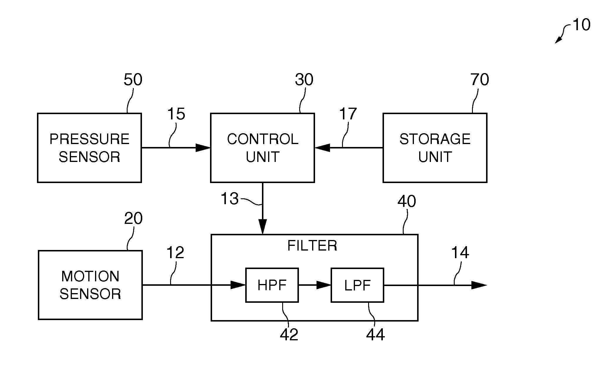
A sensor unit includes a motion sensor which detects a motion of an object, outputs a detection value, and is mounted on the object through an attachment, a filter which receives the detection value, passes a given frequency band, and is able to change a cutoff frequency of the frequency band, and a control unit which controls the cutoff frequency, wherein the control unit determines the cutoff frequency in accordance with hardness of the attachment.

Description

BACKGROUND[0001]1. Technical Field[0002]The present invention relates to a sensor unit, a motion analysis device using the sensor unit, and the like.[0003]2. Related Art[0004]In a motion sensor which detects a motion of an object, the accuracy of a motion to be detected may change depending on a mounting method on the object. JP-A-2009-125507 describes a technique in which an object for motion detection is a person who makes a golf swing, and a motion sensor is put directly on the ear to detect an accurate motion of a head of the person.[0005]However, when an object is a person, the person may be unwilling to bring the motion sensor into direct contact with the skin. When an object is, for example, an expensive item or a precious item, there is a need for avoiding the direct attachment of the motion sensor to the object. Even when an object is an item which is used in an athletic competition, the mounting of the motion sensor during the competition is banned by regulations, and ther...

Claims


Application Information

Patent Timeline
IPC IPC(8): G01P1/02
CPCG01P1/02G01P13/00G01L5/10G01L1/18A61B5/6895A61B5/721A61B5/11
Inventor SATO, MASATOSHI
Owner SEIKO EPSON CORP
Learn More