
Lifting and leveling insert for a precast concrete slab

a technology of precast concrete and inserts, which is applied in the field can solve the problems of precast concrete slabs that must be level, wear of tires, heavy damage to vehicles, etc., and achieve the effect of reducing the likelihood of buckling and reducing the moment for

Inactive Publication Date: 2019-06-04
MEADOW BURKE
View PDF78 Cites 6 Cited by
  • Summary
  • Abstract
  • Description
  • Claims
  • Application Information

AI Technical Summary

Benefits of technology

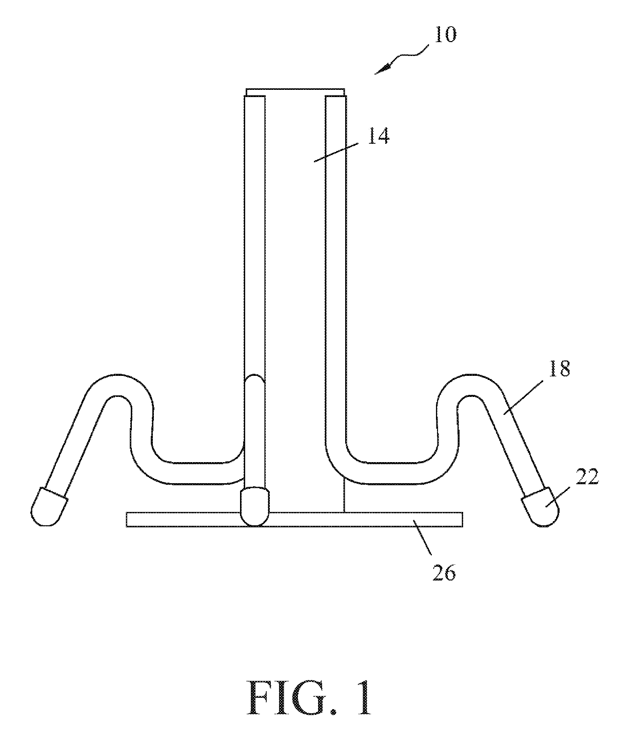
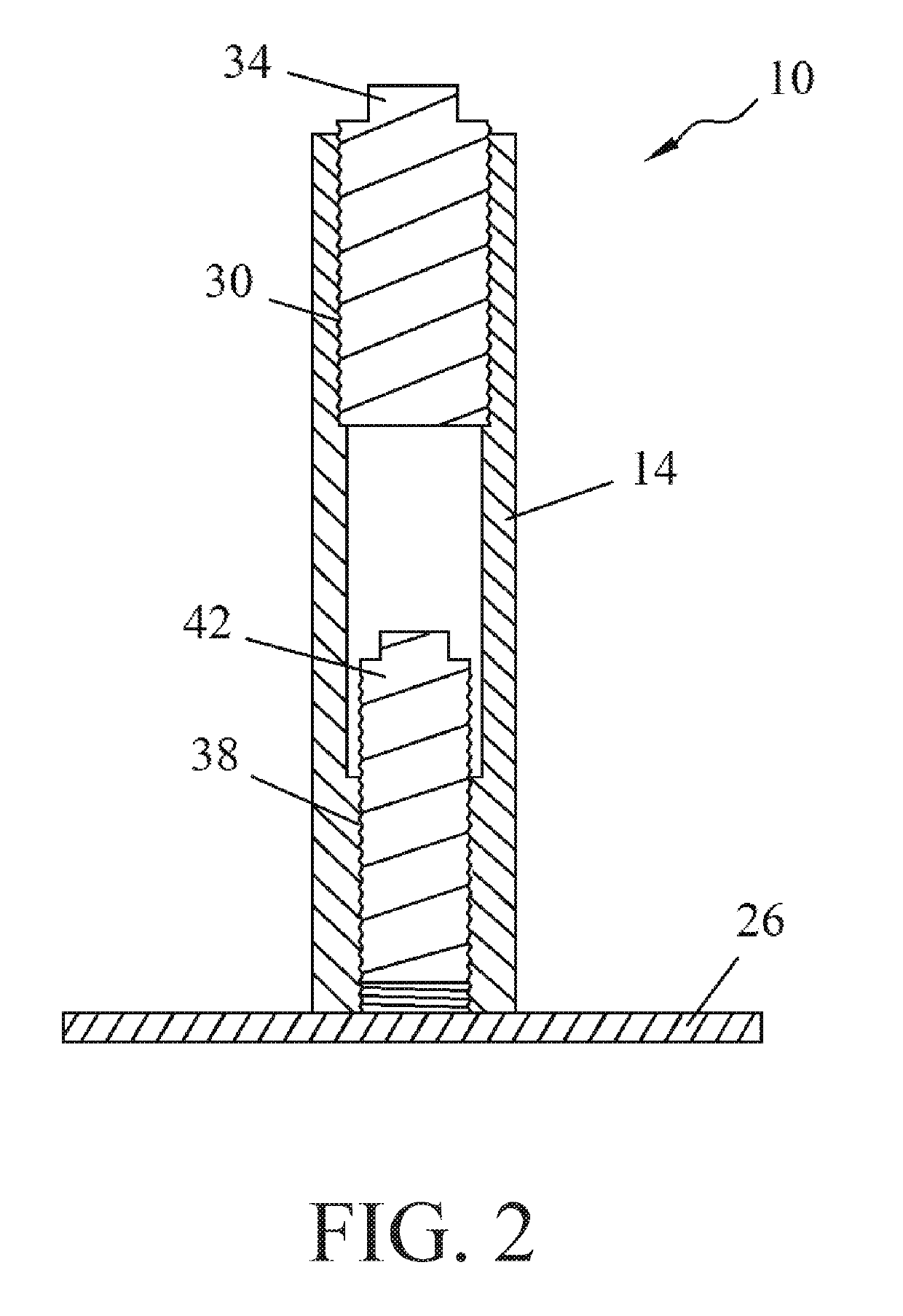
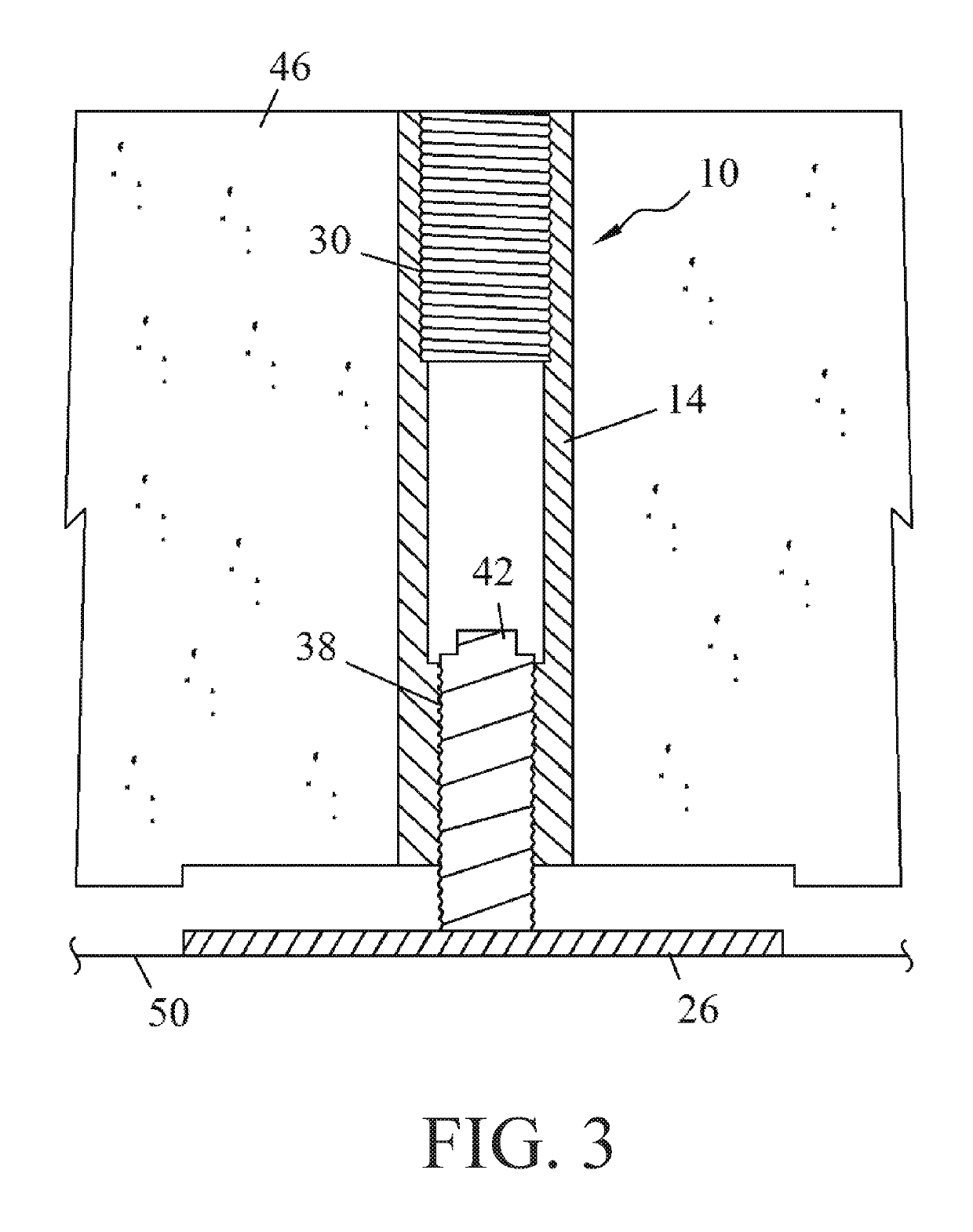
[0006]It is thus an aspect of embodiments of the present invention to provide an insert embedded in a precast concrete slab that has a two-bolt design for lifting and then leveling the precast concrete slab. The sleeve portion of the insert has two distinct threaded portions along the longitudinal length of the sleeve to accommodate the two-bolt design. A first lifting bolt is inserted into a first threaded portion proximate to the top surface (road side) of the precast concrete slab for transporting the slab. Then a second leveling bolt is used in a second threaded portion that is proximate to the bottom surface of the slab, and engagement of the second bolt causes a plate to raise the precast concrete slab relative to the road surface or any other ground surface. The two-bolt design can use shorter, and thus, stiffer bolts to reduce the likelihood of buckling and reduce the moment forces on the bolts.
[0008]It is a further aspect of embodiments of the present invention to provide an insert for lifting and leveling a precast concrete slab where the point of engagement for the lifting bolt and the leveling bolt is proximate to the upper surface and the lower surface, respectively, of the precast concrete slab. This close positioning between the bolts and the relevant bearing surfaces creates a more robust system. For example, the lifting system that lifts and moves the concrete slab through the lifting bolt imposes a moment force on the lifting bolt when a cable that connects to the lifting bolt is out of plumb or forms an angle with the concrete slab, specifically, the longitudinal axis of the sleeve. Since the lifting bolt engages the threaded portion near the upper surface of the slab, the moment force is reduced. Similarly, the leveling bolt engages a plate at the lower surface of the slab, and drives the plate into a ground surface. Because the leveling bolt engages a threaded portion that is proximate to the lower surface of the slab, there is a reduced likelihood of the leveling bolt buckling under a large force.
[0009]It is an aspect of embodiments of the present invention to provide an insert for lifting and leveling a precast concrete slab where a plate is affixed to the insert via a plug. The plug can provide a severable interconnection to the concrete slab in a number of ways, including being threaded into the lower threaded portion of the sleeve and a friction fit in the sleeve. The plug in some embodiments may be a plastic such as polymer. The plug simplifies installation of the insert in a concrete slab since all of the parts of the insert are secured together before setting the insert in the slab. During operation, the leveling bolt travels out of the bottom surface of the insert and clears the plug out of the lower threaded insert. The plate detaches from the sleeve of the insert, and then the leveling bolt can drive the plate into the ground surface to raise part of the concrete slab to align the concrete slab as needed. In further embodiments, the plate may be operably interconnected to the sleeve or other portion of the insert by, for example, an adhesive, wires, tubular spacers, etc.

Problems solved by technology

One issue with using precast concrete slabs to repair roads is that the precast concrete slab must be level with the other portions of the road.
A misaligned precast concrete slab can wear a tire or even cause heavy damage to a vehicle.
Accordingly, the bolt must be long enough to extend through the entire concrete slab, and therefore, the bolt has a potential risk of buckling or being subjected to a large moment force as the eyelet or top of the bolt is lifted and moved by cables.
Even having just one bolt buckle can hinder the ability of the precast concrete slab to align with a road surface.
This results in a loss of time, which defeats the advantage of having a precast concrete slab.

Method used


Image

  • Lifting and leveling insert for a precast concrete slab
  • Lifting and leveling insert for a precast concrete slab
  • Lifting and leveling insert for a precast concrete slab

Examples


Embodiment Construction

[0041]The invention has significant benefits across a broad spectrum of endeavors. It is the Applicant's intent that this specification and the claims appended hereto be accorded a breadth in keeping with the scope and spirit of the invention being disclosed despite what might appear to be limiting language imposed by the requirements of referring to the specific examples disclosed. To acquaint persons skilled in the pertinent arts most closely related to the invention, a preferred embodiment that illustrates the best mode now contemplated for putting the invention into practice is described herein by, and with reference to, the annexed drawings that form a part of the specification. The exemplary embodiment is described in detail without attempting to describe all of the various forms and modifications in which the invention might be embodied. As such, the embodiments described herein are illustrative, and as will become apparent to those skilled in the arts, and may be modified in...


PUM


Abstract

An insert for lifting and leveling a precast concrete slab is provided. The insert includes a sleeve that extends through the concrete slab and has two distinct threaded portions on an inner surface of the sleeve. This configuration allows a lifting bolt to be positioned into an upper end of the sleeve to lift the concrete slab, and a different-sized leveling bolt to be positioned in the sleeve to selectively elevate or raise part of the concrete slab relative to a ground surface.

Description

CROSS-REFERENCE TO RELATED APPLICATIONS[0001]This U.S. Non-Provisional Patent Application is a Continuation-in-Part of and claims priority to U.S. patent application Ser. No. 15 / 656,486, filed Jul. 21, 2017, which claims priority to U.S. Provisional Patent Application No. 62 / 365,271 filed Jul. 21, 2016, the entire disclosures of which are hereby incorporated by reference in their entirety.FIELD OF THE INVENTION[0002]This invention generally relates to precast concrete slabs and specifically to systems and devices embedded in precast concrete slabs that adjust the elevation of the concrete slab relative to a ground surface.BACKGROUND OF THE INVENTION[0003]Precast concrete slabs provide convenience to contractors and builders since precast concrete slabs can be manufactured offsite. Instead of pouring concrete onsite and waiting for the concrete to cure, builders can buy or manufacture as many precast concrete slabs as needed, then install them onsite, which reduces the time required ...

Claims


Application Information

Patent Timeline
Patent Type & Authority Patents(United States)
IPC IPC(8): E04B1/35E04B5/04E01C19/00E01C23/10E01C5/06
CPCE04B5/04E01C23/10E01C19/00E04B2103/02E04B2005/176E01C5/001
Inventor RECKER, MICHAELNAUMANN, RONALD G.RUIZ, HECTOR G.
Owner MEADOW BURKE
Learn More