Fixing device that alleviates a physical load on non-heat-generating regions of a heat generating layer of a fixing film

a fixing film and physical load technology, applied in the field of fixing devices, can solve problems such as non-uniformity generation of heat generation

Active Publication Date: 2019-06-04
CANON KK
View PDF31 Cites 3 Cited by
  • Summary
  • Abstract
  • Description
  • Claims
  • Application Information

AI Technical Summary

Problems solved by technology

In the case in which a longitudinal end of the sliding member and the heat generating layer slide with each other, however, there is a possibility that the heat generating layer is abraded (worn) and thus, heat generation non-uniformity generates.

Method used


Image

  • Fixing device that alleviates a physical load on non-heat-generating regions of a heat generating layer of a fixing film
  • Fixing device that alleviates a physical load on non-heat-generating regions of a heat generating layer of a fixing film
  • Fixing device that alleviates a physical load on non-heat-generating regions of a heat generating layer of a fixing film

Examples


embodiment 1

Image Forming Apparatus 111

[0022]With reference to FIG. 12, an image forming apparatus 111 in which a fixing device F in this embodiment according to the present invention is mounted will be described. FIG. 12 is a sectional view showing a schematic structure of an example of the image forming apparatus (monochromatic laser printer in this embodiment) 111 using an electrophotographic recording technology.

[0023]In the image forming apparatus 111, an image forming portion IF for forming an image on a recording material P includes a photosensitive drum 100 as an image bearing member, a charging member 102, and a laser scanner 103. Further, the image forming portion IF includes a developing device 104, a cleaner 101 for cleaning an outer peripheral surface of the photosensitive drum 100, and a transfer member 106. An operation of the image forming portion IF is well known and, therefore, a detailed description will be omitted.

[0024]Incidentally, the photosensitive drum 100, the charging...

modified embodiment

[0059]As in Embodiment 1, as the material of the sliding member 2, a material having a high thermal conductivity may preferably be used. As a result, in the case in which a temperature of a non-sheet-passing region through which a large-sized recording material P passes, but a small-sized recording material P does not pass, becomes high, heat in the non-sheet-passing region is conducted to a sheet-passing region in which the temperature is relatively low, so that an effect of uniformizing the temperature non-uniformity of the film 1 with respect to the rotational direction of the film 1 is obtained.

[0060]Also, the heat supplied to the non-sheet-passing region of the small-sized recording material is transmitted (conducted) to the small-sized recording material through the sliding member 2, and, therefore, overheating of the non-sheet-passing region can be suppressed, so that even on the small-sized recording material P, the image can be fixed at an output speed equal to or somewhat ...

embodiment 2

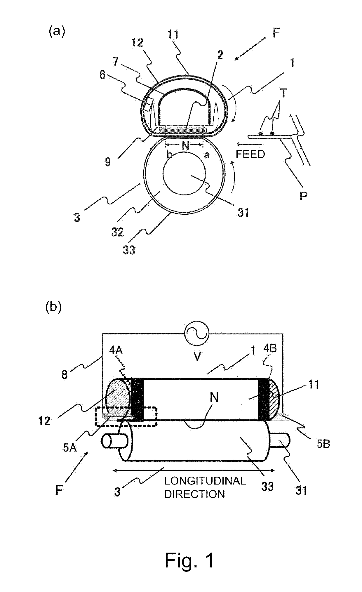
[0067]A second embodiment of the fixing device F will be described. In this embodiment, only a constitution different from the constitution of Embodiment 1 will be described.

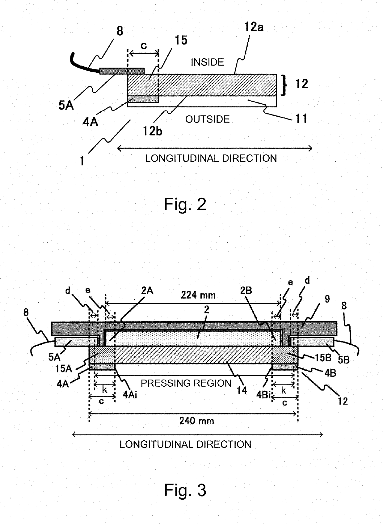
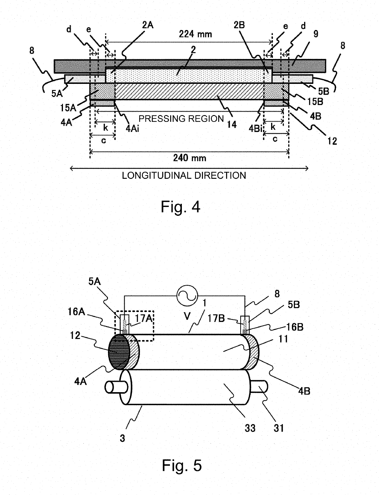
[0068]FIG. 5 is a perspective view showing a schematic structure of the fixing device F. FIG. 6 is a sectional view of a film 1 at a rectangular portion indicated by a broken line in FIG. 5. FIG. 7 is a sectional view showing a positional relationship among a heat generating layer 12 of the film 1, a sliding member 2, and a guiding member 9.

Film 1

[0069]As regards the film 1, with respect to the longitudinal direction perpendicular to the feeding direction of the recording material P, electroconductive layers 4A and 4B formed on the outer peripheral surface 12b of the heat generating layer 12 at both end portions of the film 1 are exposed. As a result, the heat generating layer 12 can be energized from the outer peripheral surface of the film 1 by energizing members 5A and 5B through the electroconductive layers ...


PUM


Abstract

A fixing device includes a cylindrical film including a heat generating layer and an electroconductive layer electrically connected with the heat generating layer. A volume resistivity of the electroconductive layer is less than a volume resistivity of the heat generating layer. The fixing device further includes an energizing member, a roller, a sliding member, and a supporting member. A thermal conductivity of the sliding member is greater than a thermal conductivity of the supporting member. A recording material on which a toner image is formed is heated while being fed through a nip. A longitudinal end of the sliding member is positioned between an inner end surface and an outer end surface of the electroconductive layer with respect to the longitudinal direction of the film.

Description

[0001]This application claims the benefit of Japanese Patent Application No. 2016-248967 filed on Dec. 22, 2016, which is hereby incorporated by reference herein in its entirety.FIELD OF THE INVENTION AND RELATED ART[0002]The present invention relates to a fixing device to be mounted in an image forming apparatus, such as an electrophotographic copying machine or an electrophotographic printer.[0003]As the fixing device mounted in the electrophotographic copying machine or printer, a fixing device of a film heat generation type using a film that generates heat by energization has been known. The fixing device of this type includes a cylindrical film including a heat generating layer generating heat by energization, an energizing member for energizing the heat generating layer, a sliding member sliding on an inner peripheral surface of the film, and a pressing roller for forming a nip between itself and the film in cooperation with the sliding member. A recording material on which an...

Claims


Application Information

Patent Timeline
Patent Type & Authority Patents(United States)
IPC IPC(8): G03G15/20
CPCG03G15/2057G03G15/2042
Inventor AN, KOJINARAHARA, TAKASHISHINJI, TAKESHIIMAIZUMI, TORUDODA, KAZUHIROWAKATSU, KOHEI
Owner CANON KK
Why Eureka
Try Eureka