
Modular base station architecture for wireless sensor network

a wireless sensor network and module technology, applied in the field of internet of things, can solve the problems of limited scalability of existing gateways for the deployment of wireless sensor networks, gateways generally providing only limited connectivity, and no longer suitable for wireless sensor networks. achieve the effect of increasing the load capacity of radio interface devices

Active Publication Date: 2019-06-04
KERLINK
View PDF11 Cites 1 Cited by
  • Summary
  • Abstract
  • Description
  • Claims
  • Application Information

AI Technical Summary

Benefits of technology

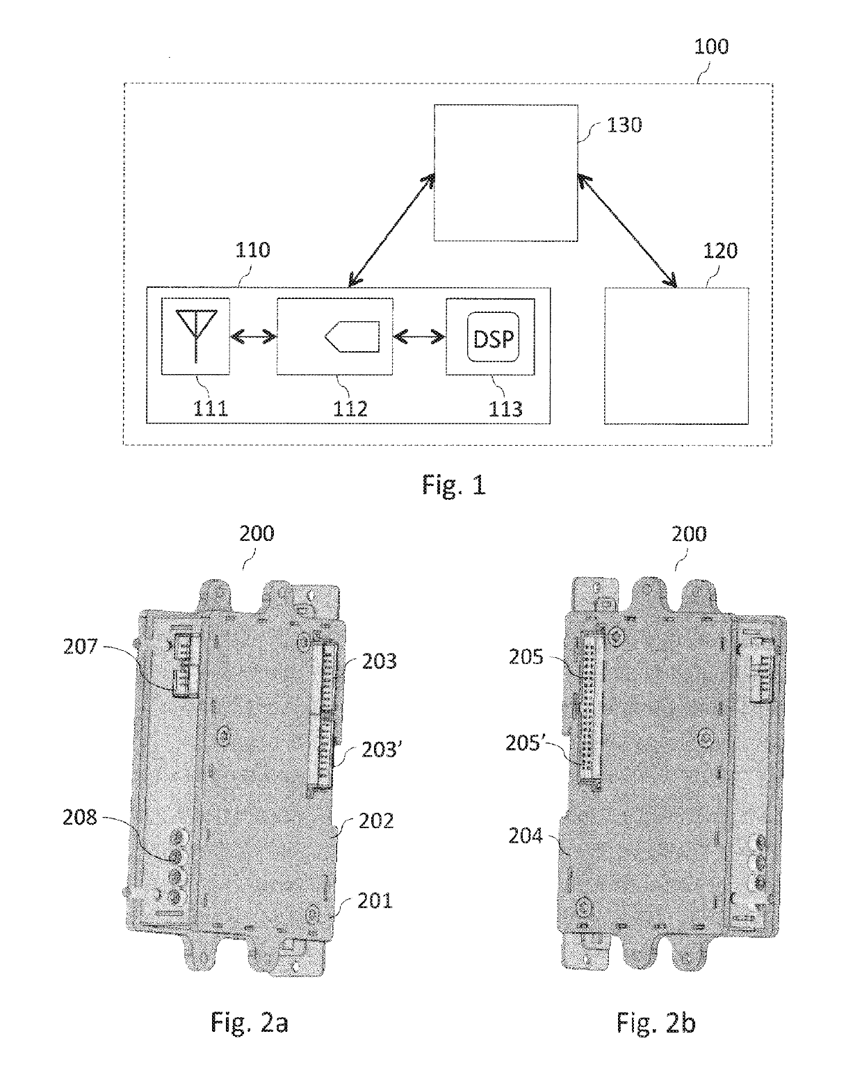
The proposed technique involves a digital radio modem and an analog radio interface module that work together to create a flexible and modular radio interface device. The digital radio modem has its own dedicated frame with different communication interfaces, making it easy to assemble or disassemble in conjunction with a gateway for a wireless sensor network. It can be used with different radio access technologies and can be adapted to different situations by simply choosing the right type of digital radio modem or analog radio interface module. The combination of these different physical blocks provides a simple and effective solution for managing a large number of wireless sensors or other communication objects. The analog radio interface module can be easily connected to different antennae configurations, increasing the load capacity of the radio interface device. Overall, the proposed technique allows for easy customization and flexibility in creating a secure and efficient wireless communication network.

Problems solved by technology

Existing gateways for the deployment of wireless sensor networks have limited scalability: in general, they are designed for the management of a single type of radio access technology, in a single radio frequency band.
These gateways generally provide only limited connectivity, in terms of potential configurations of antennae, or may even dictate the use of the antenna supplied.
While these gateways are particularly appropriate for the deployment of wireless sensor networks on a small or medium scale—in contexts of application which are relatively fixed and closely-managed—they are no longer suitable for the deployment of wireless sensor networks over very extensive and constantly changing zones—for example on the scale of an entire city—where a high degree of responsiveness and adaptability are required.
These existing gateways, which must be entirely replaced in response to the slightest requirement for a network upgrade, are therefore unable to accommodate the various issues associated with the scheduled expansion of dedicated networks for the Internet of Things: a constant and substantial increase in the number of sensors to be managed within a single territory, the diversity of radio access technologies to be accommodated, the diversity of frequency bands used, the diversity of types of antennae to be managed, etc.

Method used


Image

  • Modular base station architecture for wireless sensor network
  • Modular base station architecture for wireless sensor network
  • Modular base station architecture for wireless sensor network

Examples


Embodiment Construction

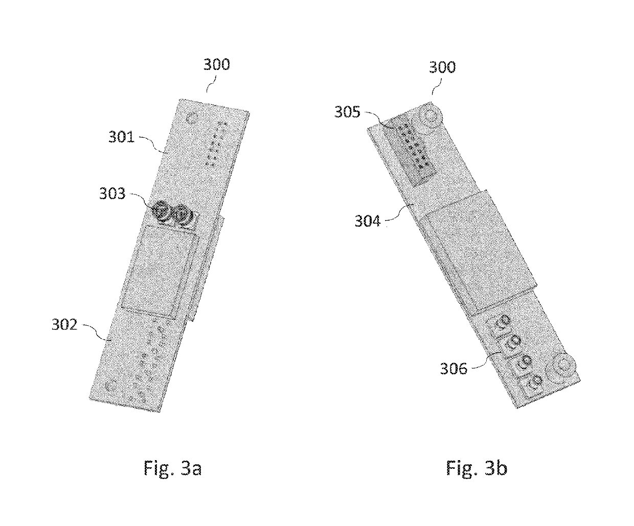
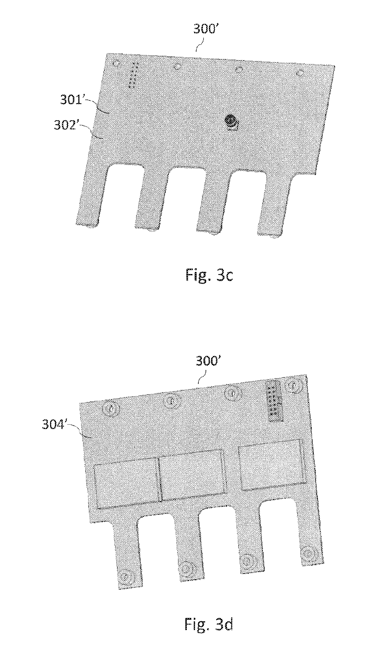
[0044]The proposed technique relates to a novel base station architecture for the deployment of sensor networks, or other communicating objects, in a wireless arrangement. Throughout the document, a base station of this type is also described as a “gateway”, and the term “wireless sensor network” is employed indiscriminately to signify a network of wireless sensors, or a network of—potentially more complex—wireless communication objects. The proposed architecture is based upon the separation of the key conventional functionalities of a gateway into different physical blocks, each of which has its own dedicated frame, within which different communication interfaces are arranged, such that these different physical blocks are interconnectable. This design not only permits the simple and rapid construction of “customized” gateways, thus permitting the fulfillment of many different types of requirements, but also endows these gateways with a high level of modularity and scalability. The ...


PUM


Abstract

A gateway architecture able to meet the challenges raised by the large-scale deployment of wireless sensor networks. The main modules within such a gateway for wireless sensor networks, for example digital radio modems and analog radio interface modules take the form of various separate physical blocks that may be joined together. This technique makes it possible to implement adaptable and scalable modular gateways that may be quickly and easily configured or suited to any situation, simply by replacing existing physical blocks or adding new physical blocks.

Description

1. FIELD[0001]The field of the invention is that of the Internet of Things. More specifically, the invention relates to a gateway architecture which permits the deployment of wireless sensor networks, specifically on a large scale, and to the interconnection of such networks with other networks such as, for example, the Internet.2. PRIOR ART[0002]The Internet of Things is developing rapidly. This development is accompanied by the emergence of new applications, which extend beyond the traditional scope of homes or businesses and are integrated in far larger infrastructures. Specifically, the concept of “smart cities” falls within the context of this development. By the large-scale deployment of wireless sensor networks, or other communicating objects, it becomes possible to offer new services to individuals, or to the authorities responsible for municipal administration. The range of possibilities is extensive. In this way, street lighting can be optimized, for example by the adaptat...

Claims


Application Information

Patent Timeline
Patent Type & Authority Patents(United States)
IPC IPC(8): H04B1/00H04W88/16H04B7/24G06F1/18H05K5/00H04B1/3816H04L12/28H04W84/18
CPCH04B1/0003G06F1/18H04B1/005H04B7/24H04W88/16H05K5/0021H04B1/3816H04W84/18H04W88/10
Inventor CHAPLET, MARTINGILBERT, MICHELNICOLAS, SAMUELDUBOURG, RONANDELIBIE, YANNICK
Owner KERLINK
Learn More