Pump drivetrain damper system and control systems and methods for same

a technology of damper system and pump drivetrain, which is applied in the direction of positive displacement liquid engine, pump, liquid fuel engine, etc., can solve the problems of pump drivetrain and other equipment coupled, pump drivetrain vibration, damage to the pump drivetrain, etc., and achieve the effect of reducing vibration

Active Publication Date: 2019-06-11
SPM OIL & GAS INC
View PDF273 Cites 138 Cited by
  • Summary
  • Abstract
  • Description
  • Claims
  • Application Information

AI Technical Summary

Benefits of technology

[0012]In a second aspect, there is provided a method of dampening vibrations in a pump drivetrain, the pump drivetrain comprising a driveshaft, a transmission operably coupled to the driveshaft, and an engine operably coupled to the transmission. The method includes: detecting a beginning of torque variation in the pump drivetrain; sending one or more control signals to one or more electromagnets in response to detecting the beginning of the torque variation in the pump drivetrain; and negating, using the one or more electromagnets, at least a portion of the torque variation to prevent an unacceptable generation of inertia in one or more of the driveshaft, the transmission, and the engine due to the torque variation.
[0018]In a third aspect, there is provided a method of dampening vibrations, the method comprising: receiving, from one or more sensors, signals or data associated with characteristics of at least one reciprocating pump assembly; calculating, using one or more processors and based on the sensor signals or data, torque characteristics of one or more of the reciprocating pump assembly and an engine operably coupled thereto; calculating, using the one or more processors and based on the torque characteristics, damper response voltages per degree of crank angle; and sending one or more control signals to one or more electromagnets to dampen vibrations in one or more of the reciprocating pump assembly and the engine, wherein the one or more control signals are based on the damper response voltages per degree of crank angle.
[0032]In a fourth aspect, there is provided a damper system for a fluid pump, the damper system comprising: a housing defining a fluid chamber, the fluid chamber configured to receive a magnetorheological fluid therein; a flywheel disposed at least partially within the fluid chamber and adapted to be operably coupled to a crankshaft of the fluid pump; and a magnetic device secured to the housing and positioned proximate to the flywheel; wherein the magnetic device applies a variable drag force to the flywheel to reduce vibration in the fluid pump when the magnetorheological fluid is received in the fluid chamber, the flywheel is operably coupled to the crankshaft, and the magnetic device is energized.
[0074]In a tenth aspect, there is provided a reciprocating pump assembly that includes a power end housing and a fluid end housing; a plunger; a drivetrain for reciprocating the plunger between the power end housing and the fluid end housing; a damper system, the damper system comprising: a stationary housing defining a fluid chamber, the fluid chamber configured to receive a magnetorheological fluid therein; a flywheel disposed at least partially within the fluid chamber; and a magnetic device secured to the housing and positioned proximate to the flywheel, the magnetic device, when energized, applies a variable drag force to the flywheel to reduce vibration in the fluid pump.

Problems solved by technology

During operation, vibration occurs in the pumps, the pump drivetrain and other equipment coupled to the pump drivetrain.
Excessive vibration causes damage to the pump drivetrain and can damage the pumps and other equipment coupled to the pump drivetrain.
Furthermore, such vibrations can accelerate wear on parts of the drivetrain, such as the transmission, resulting in the need to replace these parts before other parts of the pump drivetrain are ready for replacement or servicing.
When components of the pump drivetrain fail, replacement components must be substituted at significant cost to well operators.
In some instances, well operators plan for this type of failure by obtaining standby components, which further increases the costs of operating the well.
In some cases, the pump drivetrain experiences resonance vibration, which can cause extensive damage to pump components, as well as potential hazards to nearby workers.
However, current dampers do not adequately dampen vibrations and often do not dampen vibrations until the vibrations have gained momentum in the drivetrain.
In addition, current dampers require large, heavy components to counteract vibrations in the pump drivetrain.
Due to current weight limits on vehicles used to transport equipment to and from well sites, such as frac trucks, current dampers can cause the frac trucks to be overweight, thus requiring road permits for transportation of the frac equipment.
In addition, current dampers containing large, heavy parts are often difficult to couple to a pump drivetrain and, when coupled to a pump assembly, are difficult to remove and service.

Method used


Image

  • Pump drivetrain damper system and control systems and methods for same
  • Pump drivetrain damper system and control systems and methods for same
  • Pump drivetrain damper system and control systems and methods for same

Examples


Embodiment Construction

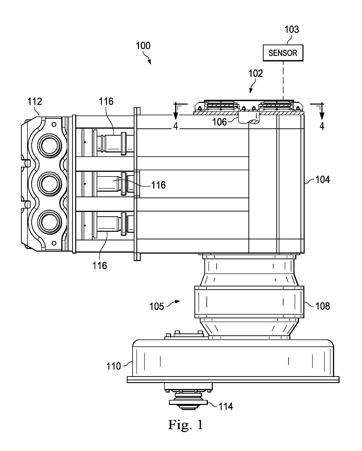
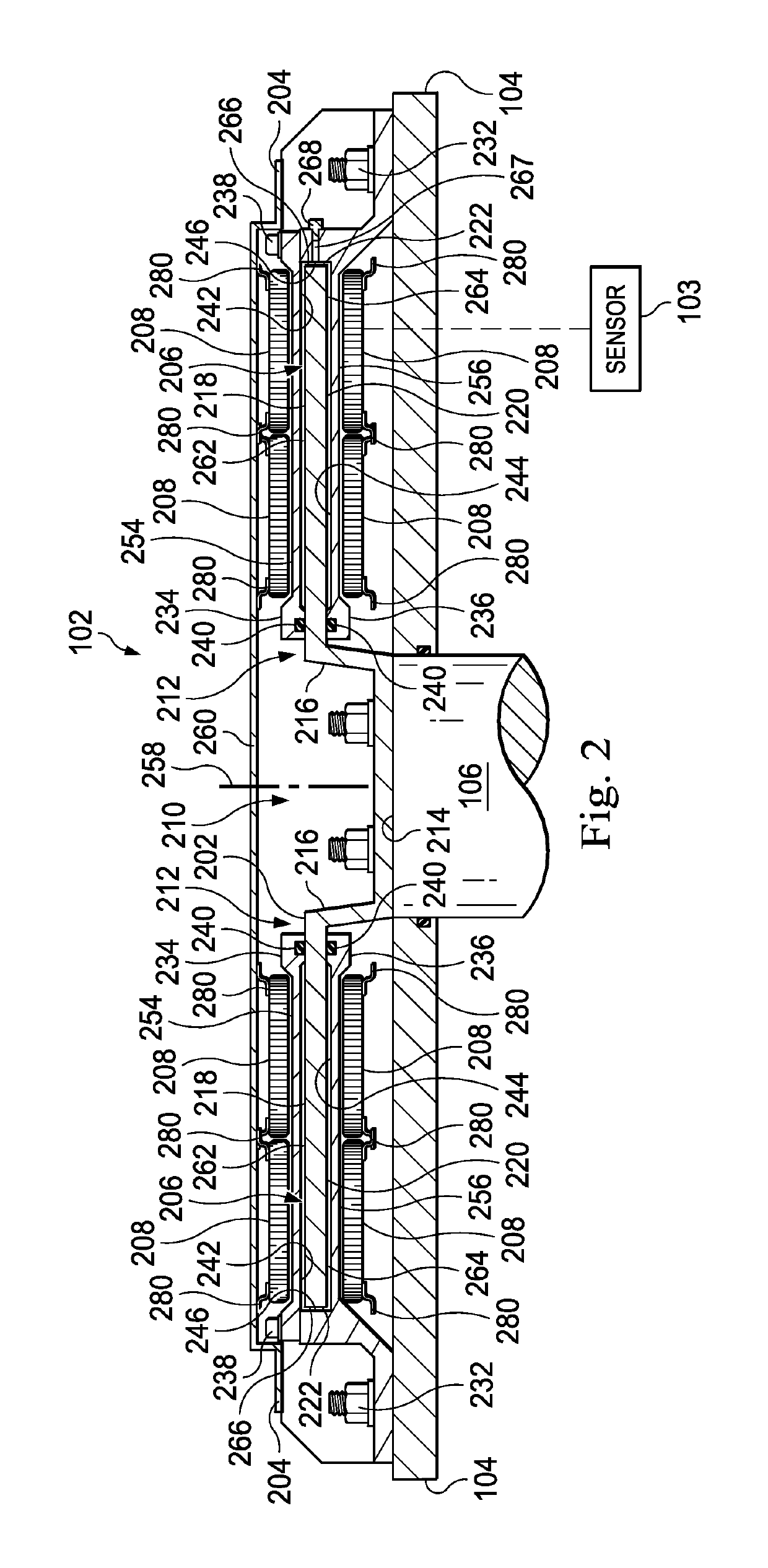
[0107]FIG. 1 illustrates an embodiment of a reciprocating pump assembly 100 having a damper system 102 to reduce vibrations in the pump assembly 100 and an associated pump drivetrain 105. In the embodiment illustrated in FIG. 1, the reciprocating pump assembly 100 includes a power end or crankshaft housing 104, a fluid end housing 112, and a plurality of plungers 116 reciprocatingly movable toward and away from fluid end housing 112. In operation, a motor (not illustrated) rotates a crankshaft 106 disposed within the power end housing 104 to facilitate the reciprocating movement of the plungers 116. In one embodiment, the crankshaft 106 is cammed so that each respective plunger 116 reciprocates at alternating times, which helps minimize the primary, secondary, tertiary, etc. forces associated with the reciprocating pump assembly 100.

[0108]In the embodiment illustrated in FIG. 1, the reciprocating pump assembly 100 is coupled to the pump drivetrain 105 that includes gear reducers 108...


PUM


Abstract

In one aspect, there is provided a damper control system for a reciprocating pump assembly according to which control signals are sent to electromagnets. In another aspect, there is provided a method of dampening vibrations in a pump drivetrain according to which a beginning of torque variation is detected and at least a portion of the torque variation is negated. In another aspect, signals or data associated with pump characteristics are received from sensors, torque characteristics and damper response voltages per degree of crank angle are calculated, and control signals are sent to electromagnets. In another aspect, a damper system includes a fluid chamber configured to receive a magnetorheological fluid; a flywheel disposed at least partially within the fluid chamber and adapted to be operably coupled to a fluid pump crankshaft; and a magnetic device proximate the flywheel. The magnetic device applies a variable drag force to the flywheel.

Description

CROSS-REFERENCE TO RELATED APPLICATIONS[0001]This application claims the benefit of the filing date of, and priority to, U.S. patent application No. 62 / 018,310, filed Jun. 27, 2014, the entire disclosure of which is hereby incorporated herein by reference.[0002]This application claims the benefit of the filing date of, and priority to, U.S. patent application No. 62 / 019,610, filed Jul. 1, 2014, the entire disclosure of which is hereby incorporated herein by reference.TECHNICAL FIELD[0003]This disclosure relates to damper systems and methods for well servicing pumps, and in particular, to damper systems and methods for reducing vibration in reciprocating pump assemblies.BACKGROUND OF THE DISCLOSURE[0004]During the hydraulic fracturing of a well, fluids are pumped into wellbore casing and subterranean features using reciprocating or positive displacement pumps. The pumps are typically powered by one or more engines that are coupled to the pumps through a series of components known as ...

Claims


Application Information

Patent Timeline
Patent Type & Authority Patents(United States)
IPC IPC(8): F04B9/02F16D57/00F16D57/02F16D37/02F16D37/00F04B19/22F04B49/10F04B47/00F04B53/00F04B49/06
CPCF04B9/02F04B19/22F04B47/00F04B49/065F04B49/10F04B53/006F16D37/008F16D37/02F16D57/002F16D57/02F04B53/001F16D2037/002F04B1/07F16D2037/004F16D2037/007F04B17/05F16D2037/005
Inventor BYRNE, JOSEPH H.
Owner SPM OIL & GAS INC
Why Eureka
Try Eureka