Electrical connector with internal terminals having opposite sides located from connector internal sidewalls

a technology of internal terminals and connectors, which is applied in the direction of coupling contact members, coupling device connections, electrical apparatus, etc., can solve the problems of signal transmission failure, worse signal decay, signal decay, etc., and achieve the effect of facilitating the adjustment of electrical impedance, reducing cost and development time, and solving the problem effectively

Active Publication Date: 2019-06-11
ALL BEST PRECISION TECH
View PDF15 Cites 4 Cited by
  • Summary
  • Abstract
  • Description
  • Claims
  • Application Information

AI Technical Summary

Benefits of technology

[0007]Compared with the prior art, the electrical connector and the terminal according to the invention can be modified by changing the size of the fixed portion (e.g. the profile of the abutting portion, the hole dimension of the through hole and so on) or changing the first distance and the second distance, so as to adjust the impedance of the electrical connector. The structure design facilitate adjustment to the impedance of the electrical, which is conducive to reduction of cost and development time and effectively solves the problem in the prior art.

Problems solved by technology

Under a condition of high frequency transmission, when an electrical connector is not impedance matched with a transmission line, the electrical connector will reflect signals, leading to signal decay.
The higher the extent of the impedance mismatch becomes, the worse the signal decay becomes.
Even the signal transmission is failed.
It wastes time and increases the cost for making the electrical connector.

Method used


Image

  • Electrical connector with internal terminals having opposite sides located from connector internal sidewalls
  • Electrical connector with internal terminals having opposite sides located from connector internal sidewalls
  • Electrical connector with internal terminals having opposite sides located from connector internal sidewalls

Examples


Embodiment Construction

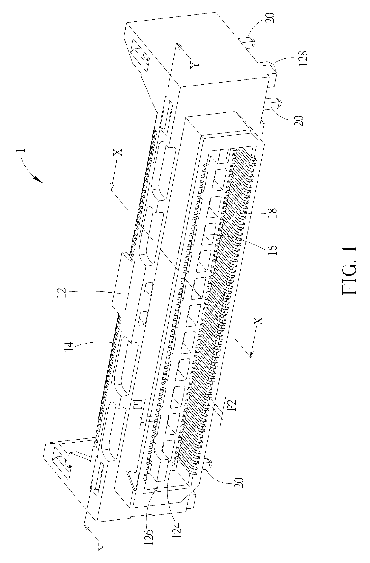
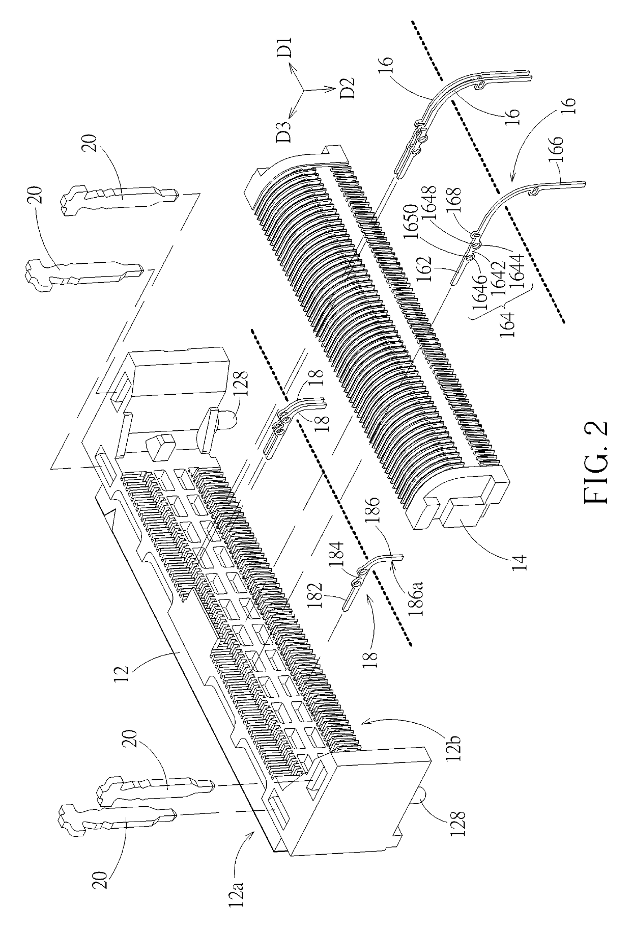
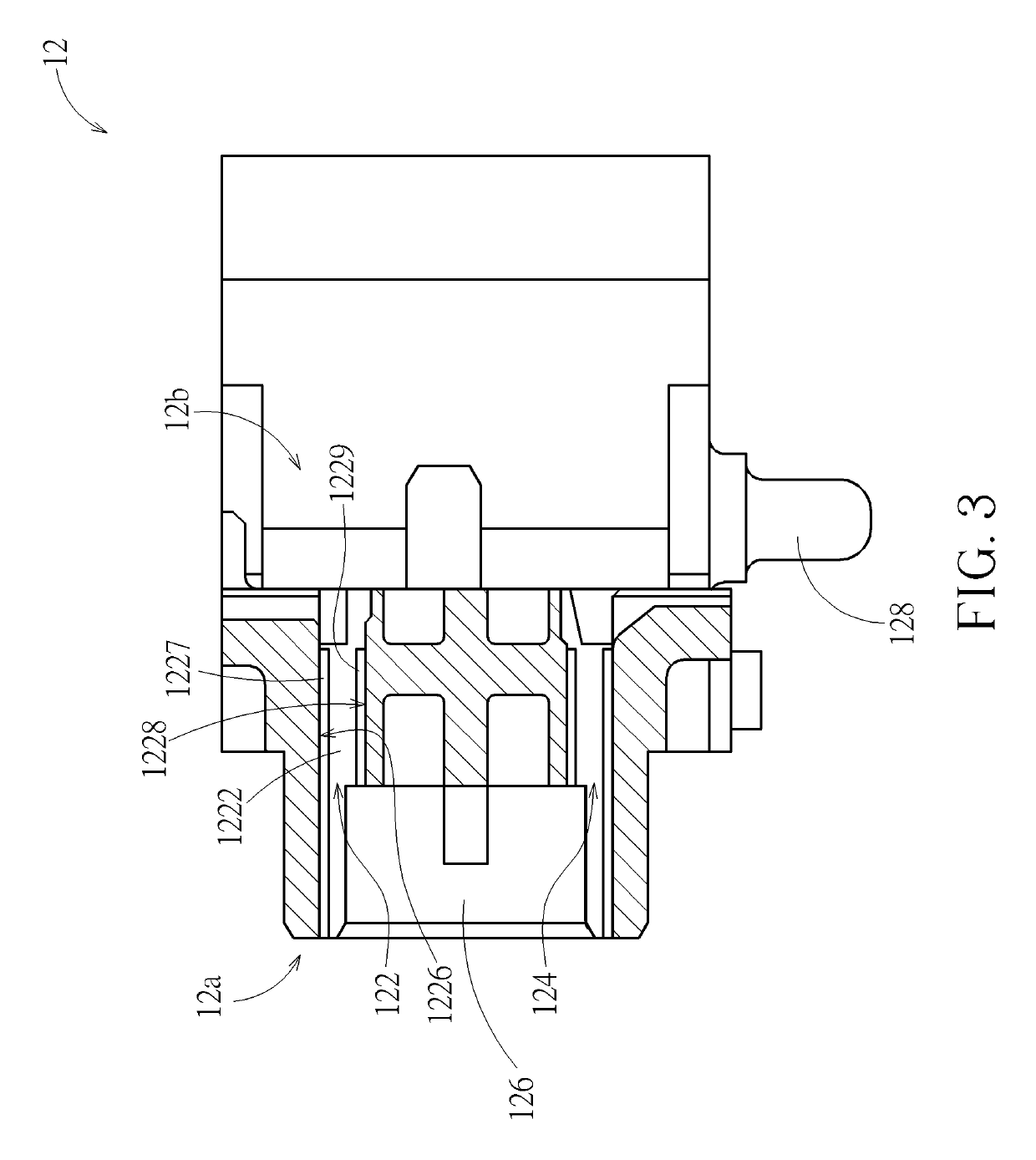
[0019]Please refer to FIG. 1 to FIG. 6. An electrical connector of an embodiment according to the invention includes an insulation housing 12, a rear cover 14, a plurality of upper row terminals 16, and a plurality of lower row terminals 18 (of which only several are shown in FIG. 2 for drawing simplification). The insulation housing 12 (e.g. but not limited to a plastic injection part) has a plurality of upper row fixing holes 122 and a plurality of lower row fixing holes 124, which are arranged in parallel and correspond to the plurality of upper row terminals 16 and the plurality of lower row terminals respectively. The upper row terminal 16 includes a contact portion 162, a fixed portion 164, and a connection portion 166. The contact portion 162 and the connection portion 166 extend from the fixed portion 164 respectively. The upper row terminal is fixed in the corresponding upper row fixing hole 122 through the fixed portion 164 such that the contact portion 162 and the connect...


PUM


Abstract

An electrical connector includes an insulation housing and at least one terminal. The insulation housing has a fixing hole that has a first inner sidewall and a second inner sidewall opposite to the first inner sidewall. The terminal includes a contact portion, a fixed portion, and a connection portion. The contact portion and the connection portion extend from the fixed portion respectively and are exposed out of the insulation housing. The fixed portion has a first side surface and a second side surface opposite to the first side surface. The fixed portion has a through hole. The fixed portion is fixed in the fixing hole with the through hole located in the fixing hole. The first and second side surfaces face the first and second inner sidewalls and are kept apart from the first and second inner sidewalls respectively.

Description

BACKGROUND OF THE INVENTION1. Field of the Invention[0001]The invention relates to an electrical connector, and especially relates to an electrical connector with tuned impedance terminals.2. Description of the Prior Art[0002]Electrical connectors are widely used in various electronic devices. By the electrical connectors, electronic devices or components in an electronic device can be electrically connected and transmit signals therebetween. As the frequency for transmitting signals becomes higher, the impedance of the electrical connector produces an increasing effect on the signal transmission. Under a condition of high frequency transmission, when an electrical connector is not impedance matched with a transmission line, the electrical connector will reflect signals, leading to signal decay. The higher the extent of the impedance mismatch becomes, the worse the signal decay becomes. Even the signal transmission is failed. The structure designs of current electrical connectors ar...

Claims


Application Information

Patent Timeline
Patent Type & Authority Patents(United States)
IPC IPC(8): H01R13/6474H01R13/422H01R12/70H01R13/05
CPCH01R13/6474H01R13/422H01R12/707H01R13/057H01R12/724H01R13/6476H01R2107/00
Inventor YANG, HAVEN
Owner ALL BEST PRECISION TECH
Why Eureka
Try Eureka