Dual centrifuge rotor with damping mass

Active Publication Date: 2019-06-18
ANDREAS HETTICH GMBH & CO KG
View PDF30 Cites 2 Cited by
  • Summary
  • Abstract
  • Description
  • Claims
  • Application Information

AI Technical Summary

Benefits of technology

The invention aims to address issues in dual centrifuges by increasing the overall mass of the rotor and synchronizing the movement of multiple rotary units. This is achieved by adding damping masses or aligning the sample container receptacle and sample containers in an identical manner relative to the rotor. The technical effect is that the resulting imbalances in the sample containers are minimized, and the overall rotor unit remains technically acceptable.

Problems solved by technology

These rapid movements of material in the containers will result in uneven loads, and thus imbalances, in the dual centrifuge.
The high rotary speeds required for numerous homogenization, mixing or grinding processes then result in correspondingly large mass imbalances.
The orientation of the sample containers may be a major cause for imbalances in the rotor.
If the longitudinal axis of the sample container is not aligned concentrically with or parallel to the axis of rotation of the rotary unit, there will be a higher risk of imbalances occurring in the rotor.
On the other hand, an asynchronous arrangement of the sample containers in the individual rotary units will increase the adverse effect of the mass imbalances since the mass movements in the sample containers cannot possibly be synchronous.
These imbalances which are required for the process not only result in noise and disruptive vibrations but also lead to premature wear and tear of mechanical components—which adversely affects the safety of the centrifuge and results in unnecessary costs.
Moreover, the quality of the sample material to be produced is also compromised by the presence of imbalances in excess of the extent necessary.

Method used


Image

  • Dual centrifuge rotor with damping mass
  • Dual centrifuge rotor with damping mass
  • Dual centrifuge rotor with damping mass

Examples


Embodiment Construction

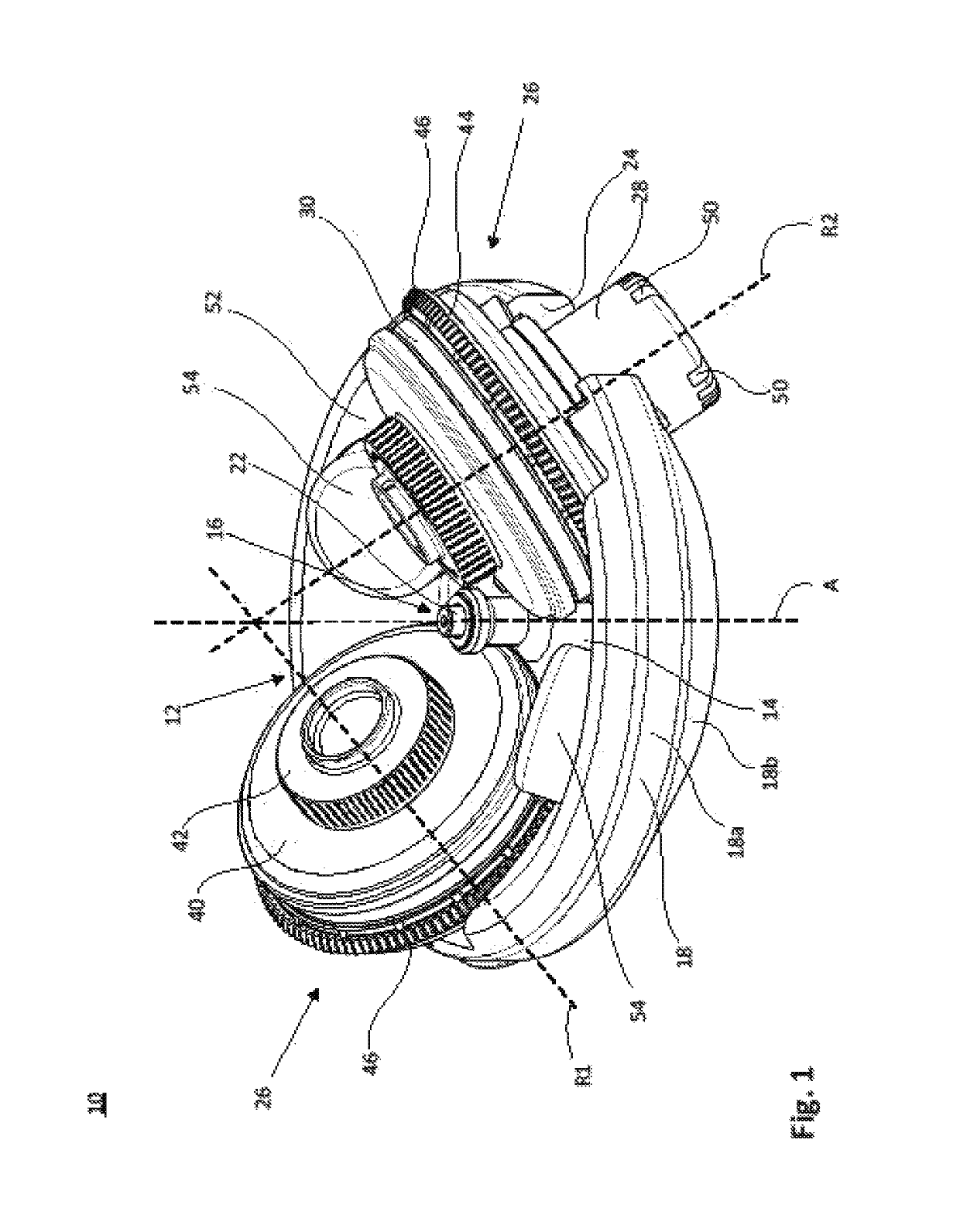
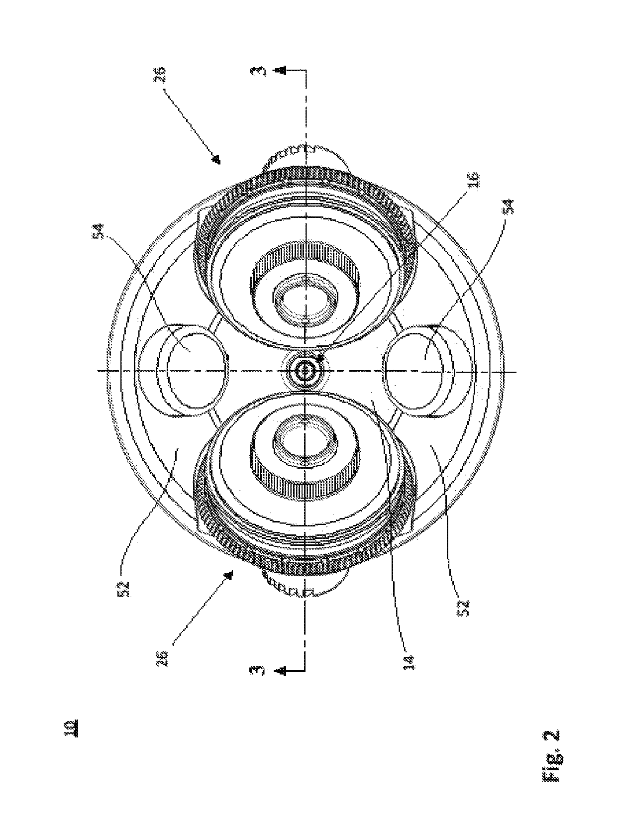
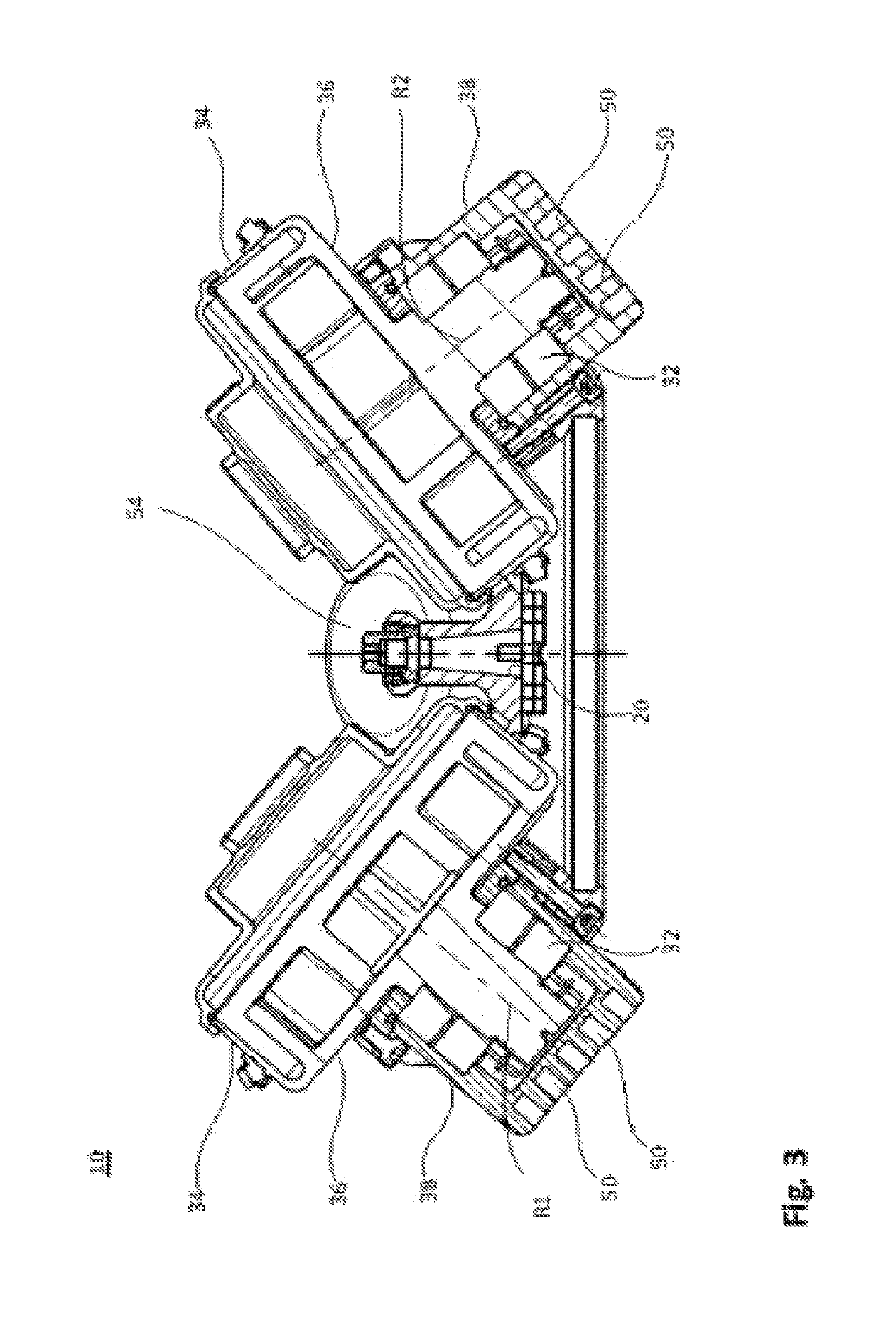
[0045]FIG. 1 is a perspective view of a rotor according to the invention 10 as part of a symmetric centrifuge with two rotary units 26 for use in a dual centrifuge not illustrated in the figures. FIG. 2 is a top view and FIG. 3 is a lateral sectional view, resp., of the rotor illustrated in FIG. 1.

[0046]The rotor 10 has a rotor head 12 of a rotationally symmetric basic shape which defines an envelope. The rotor head 12 is provided with a bottom 14 and a wall 18 that extends upwards and surrounds the bottom 14. A drive axis A extends perpendicular into the center 16 of the rotor head 12. A drive shaft not shown in the drawings has its free end extending through the rotor head 12 via an aperture 20 in the bottom 14, which aperture 20 is concentric with the drive axis A. Above the aperture 20, a receiving tube 22 is integrally formed with the bottom 14, which tube 22 serves to center and vertically fix the rotor head 12 in position on the drive shaft.

[0047]The wall 18 has a vertical po...


PUM


Abstract

A rotor (10) of a dual centrifuge which can be rotated about a drive axis (A) in a centrifuge, which rotor comprises at least two rotary units (26) that are arranged symmetrically to one another and have a bearing (32) and a rotary head (30) which is connected to the bearing (32) and which is mounted in the bearing (32) so as to be rotatable about a rotational axis (R1, R2), which rotary head (30) can be driven about the rotational axis (R1, R2) relative to the rotor by another rotary mechanism (46) of the centrifuge and has a rotary head receiving unit (80) for at least one sample container or at least one sample container receptacle (100, 110), with the rotational axis (R1, R2) of the rotary head (30) being inclined relative to the drive axis (A) of the rotor, the rotary head receiving unit (80) being designed to receive an elongated sample container receptacle (100, 110) or an elongated sample container, and the longitudinal axis of the sample container receptacle (100, 110) introduced into the rotary head receiving unit (80) or the longitudinal axis of the sample container introduced into the rotary head receiving unit (80) extending perpendicular to the axis of rotation (R1, R2) of the rotary head (30) or being oriented at an angle ranging between more than 0° and less than 90° relative to the axis of rotation. At least one connection region (52) is provided to which at least one damping mass (54) can be selectively attached either in a releasable manner or, by a fixing element, in a permanent manner for operation.

Description

CROSS-REFERENCES TO RELATED APPLICATIONS[0001]This patent application is the national phase entry of PCT / EP2015 / 077540, international application filing date Nov. 24, 2015, which claims the benefit and priority of and to German patent application no. 10 2015 100 613.8, filed Jan. 16, 2015.[0002]PCT / EP2015 / 077540, international application filing date Nov. 24, 2015 and German patent application no. 10 2015 100 613.8, filed Jan. 16, 2015 are incorporated herein by reference hereto in their entireties.FIELD OF THE INVENTION[0003]The invention relates to a dual centrifuge rotor.DESCRIPTION OF THE RELATED ART[0004]EP 2 263 654 A2 discloses a method for producing lipid-based nanoparticles as well as to kits and accessories for producing the lipid-based nanoparticles by way of homogenization in a dual asymmetric centrifuge. As may be gathered from this printed publication, better results are achieved if the longitudinal axis of a sample container containing the materials for producing the ...

Claims


Application Information

Patent Timeline
IPC IPC(8): B04B5/02B01F9/00B04B9/14B01F15/00B02C17/08B04B9/12
CPCB04B5/02B01F9/0001B01F9/0003B01F15/00824B02C17/08B04B9/12B04B9/14B01F2009/0067B01F2015/0011B01F2015/00642B01F29/10B01F29/15B01F35/50B01F29/4035B01F35/333B01F2035/352
Inventor EBERLE, KLAUS-GUENTERMASSING, ULRICHDOBOS, JOVANZIROLI, VITTORIO
Owner ANDREAS HETTICH GMBH & CO KG
Why Eureka
Try Eureka