
Linear RF ion trap with high mass resolution

a rf ion trap and mass resolution technology, applied in the field of linear ion traps, can solve the problems of inability to use resolution of mass spectrometers of this type, inconvenient operation, and high precision of high precision,

Active Publication Date: 2010-06-15
BRUKER DALTONIK GMBH & CO KG
View PDF13 Cites 2 Cited by
  • Summary
  • Abstract
  • Description
  • Claims
  • Application Information

AI Technical Summary

Benefits of technology

The present invention relates to a method for measuring ions using a mass spectrometer. The method involves arranging a number of detectors along the axis of the mass spectrometer, and measuring the mass spectra of ions ejected from the detector at different locations. The mass spectra are then combined into a sum spectrum to correct for mass shifts caused by the ejection process. The method allows for accurate and efficient measurement of the mass spectra of ions, even at high speeds. The use of multiple detectors and nonlinear resonance phenomena can enhance the efficiency of the ejection process. The individual ion currents from the detectors are amplified and digitized, and the resulting sequences of values are added together to obtain the desired mass spectrum. The time shifts caused by the ejection process are calibrated to obtain accurate mass measurements. The technical effects of the invention include improved accuracy and efficiency in mass spectrometry and faster scan methods for a given mass resolution.

Problems solved by technology

A disadvantage of this arrangement is the extraordinarily high precision necessary to give a constant form and intensity to the RF electrical field at every cross-section along the axis.
The precision of the RF field is affected by disturbing effects at both ends of the pole rod system, disturbances at the ends of the slots, and, in particular, by the mechanical precision required for the shape and spacing of the pole rods.
This means that a mass spectrometer of this type does not offer usable resolution if it has such dimensional inaccuracies.
The usable mass range is also limited, as a resolution of a single mass unit is no longer available above 2000 Daltons.
The requirement for a mechanical precision of well below one micrometer is, however, almost impossible to meet.

Method used


Image

  • Linear RF ion trap with high mass resolution
  • Linear RF ion trap with high mass resolution
  • Linear RF ion trap with high mass resolution

Examples


Embodiment Construction

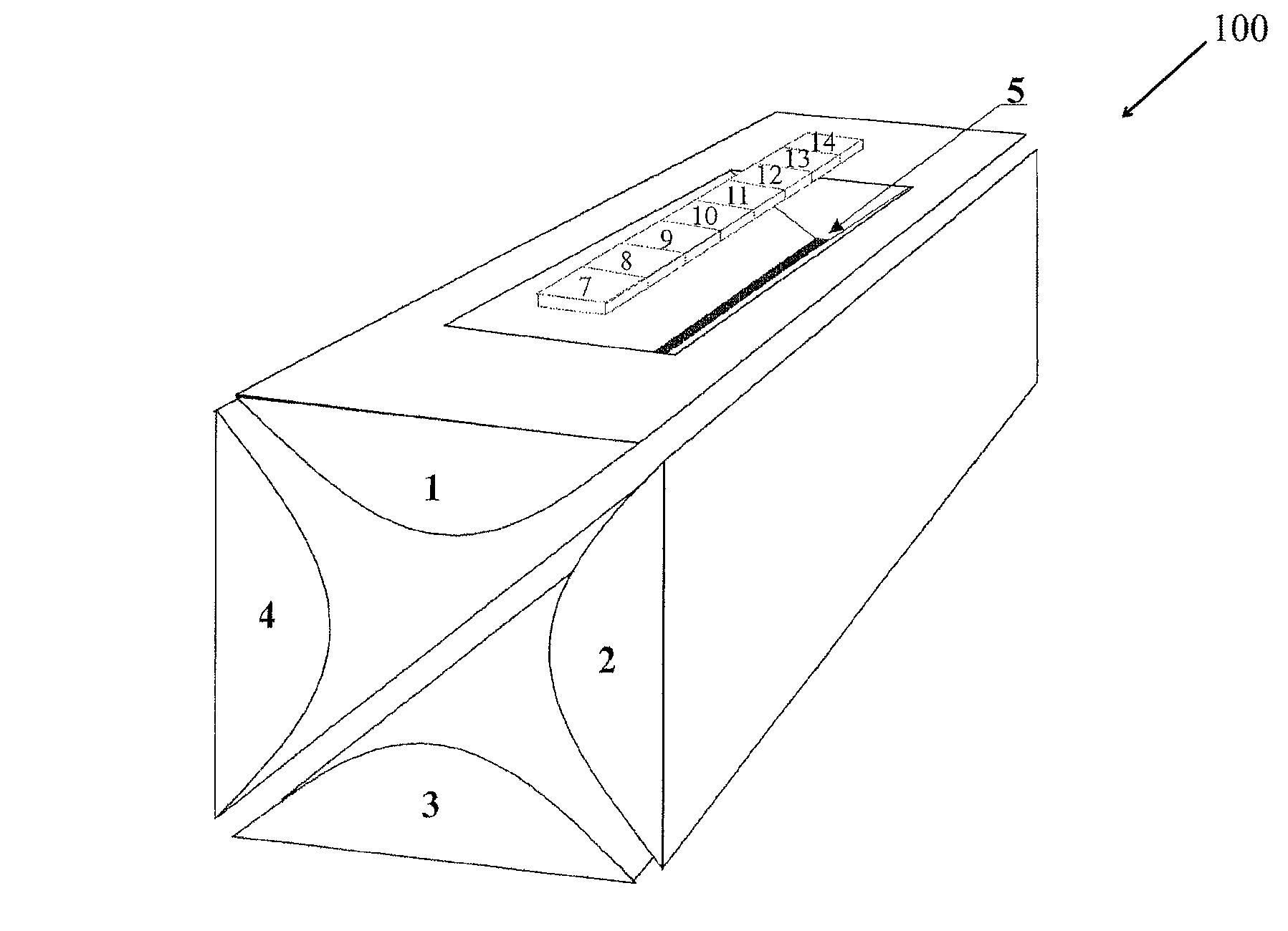
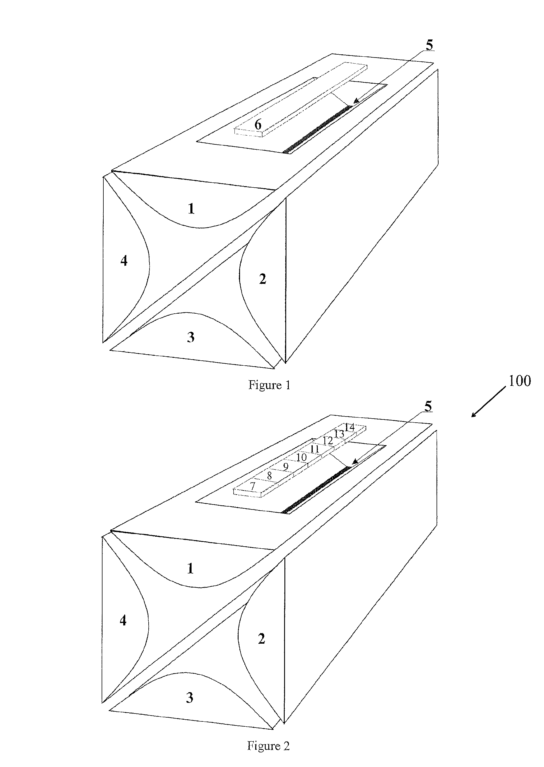
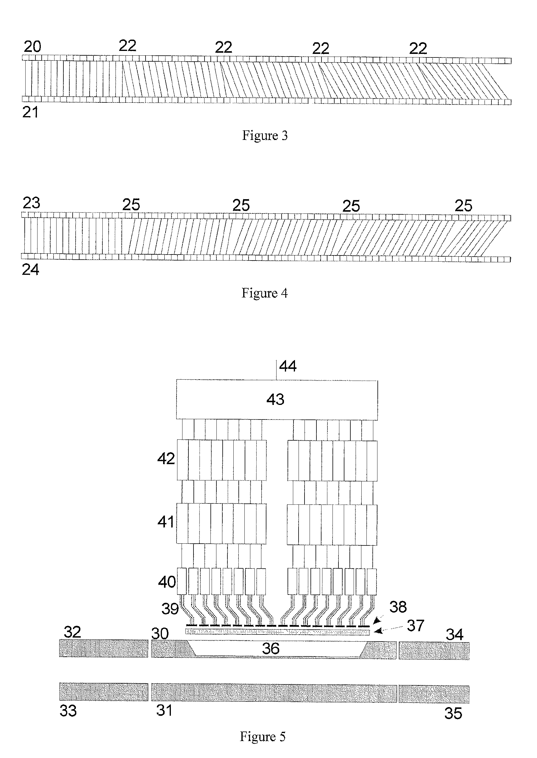
[0018]A linear ion trap 100 includes two multichannel plates that multiply secondary electrons which are each covered by a row of eight electron traps, as can be seen in FIG. 2. A mass scan involves mass-selective and mass-sequential ejection of ions, for which a variety of ejection methods known to the person skilled in the art may be applied. Each electron collector is connected to an operational amplifier that further amplifies the flow of ions from a small region along the axis of the pole rod system, and feeds the current on to an analog-to-digital converter (ADC). A plurality of (e.g., sixteen) digital location-specific mass spectra, each of which includes a long series of digital ion current values, may then be added together, one value at a time, applying an offset proportional to the mass, to each series of values in such a way that corresponding mass signals are added together to yield optimum mass resolution of the combined series of values representing the total mass spe...


PUM


Abstract

In a linear ion trap in which an essentially quadrupole RF electrical field is generated between at least four rod-shaped electrodes, ions may be mass-selectively ejected orthogonally to the axis. An aspect of the invention comprises compensating for field irregularities along the axis of a linear ion trap, which result, at different ejection locations, in the ejection of ions of the same masses at slightly different times, by of measuring the ions that are ejected at the different ejection locations using a number of separate detectors, and correcting, after a mass calibration of each of the mass spectra, the time shifts of the various location-dependent mass spectra during their addition to a combined spectrum.

Description

PRIORITY INFORMATION[0001]This patent application claims priority from German patent application 10 2006 059 697.8 filed Dec. 18, 2006, which is hereby incorporated by reference.FIELD OF THE INVENTION[0002]The invention relates to a linear ion trap in which an essentially quadrupolar RF electrical field is generated between at least four rod-shaped electrodes, and which can mass-selectively eject ions orthogonally to the longitudinal axis of the ion trap.BACKGROUND OF THE INVENTION[0003]Linear ion traps are described in U.S. Pat. No. 5,420,425 to Bier et al. A particularly preferred embodiment, which is in fact applied in a successful commercial mass spectrometer, consists in assembling four hyperbolically shaped rods to create a very precise linear quadrupole system, making slots in two opposing rods, and mass-selectively ejecting the gas-cooled ions through the slots by radial resonant excitation. If the arrangement is perfectly symmetrical, the ions then emerge, during what is ca...

Claims


Application Information

Patent Timeline
Patent Type & Authority Patents(United States)
IPC IPC(8): H01J49/42H01J49/00
CPCH01J49/423H01J49/025
Inventor MICHELMANN, KARSTEN
Owner BRUKER DALTONIK GMBH & CO KG
Learn More