Crosstalk elimination or mitigation in optical coherence tomography

a technology crosstalk, applied in the field of optical coherence tomography, to achieve the effect of reducing or minimizing a number of optical components, reducing or minimizing crosstalk induced image artifacts, and reducing the cost of at least one of manufactur

Active Publication Date: 2019-06-18
CANON USA
View PDF27 Cites 1 Cited by
  • Summary
  • Abstract
  • Description
  • Claims
  • Application Information

AI Technical Summary

Benefits of technology

[0008]Accordingly, it is a broad object of the present disclosure to provide OCT devices, systems, methods and storage mediums using an interference optical system, such as an interferometer (e.g., SD-OCT, SS-OCT, MMOCT, etc.), while mitigating, minimizing and / or adequately compensating for crosstalk noise. In accordance with one or more aspects of the present disclosure, cross-talk mitigation, minimization or compensation may be employed in double-clad fiber-based MMOCT devices or systems.
[0009]In accordance with one or more aspects of the present disclosure, there is no need to reduce system sensitivity or to use very long fiber segments (which, as aforementioned, may not be a possibility depending on a particular application). One or more embodiments of the present disclosure may also relax restrictions on core to core coupling efficiency and may match mode field diameter (MFD) at all coupling sites, which may be difficult for applications using a rotary junction for example.

Problems solved by technology

One or more embodiments of the present disclosure may also relax restrictions on core to core coupling efficiency and may match mode field diameter (MFD) at all coupling sites, which may be difficult for applications using a rotary junction for example.

Method used


Image

  • Crosstalk elimination or mitigation in optical coherence tomography
  • Crosstalk elimination or mitigation in optical coherence tomography
  • Crosstalk elimination or mitigation in optical coherence tomography

Examples


first embodiment

e Method

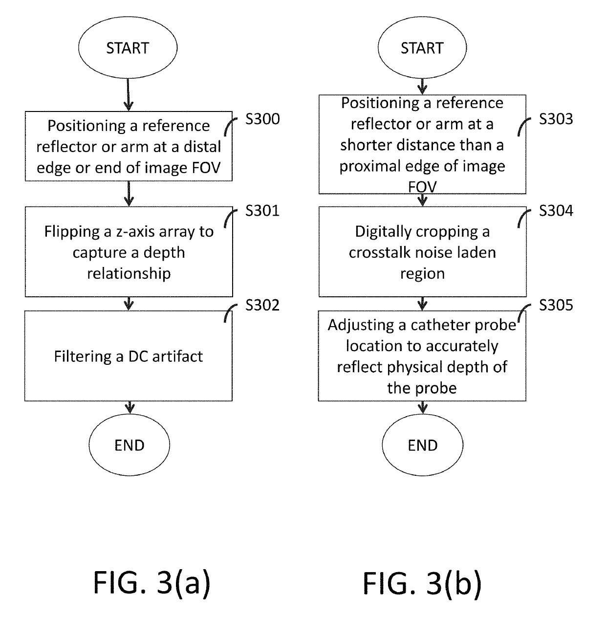
[0065]In one or more embodiments, a reference arm may be placed at the distal edge of the FOV (for example, at a predetermined depth, a maximum desired depth, etc.), such as the embodiment shown in FIGS. 6(a)-7(d), crosstalk noise artifacts no longer overlap about DC but rather alias (e.g., the signal will flip, higher frequency signals will mirror image around or about the Nyquist frequency) about the Nyquist frequency (see e.g., FIG. 7(c)). For instance, a multimodality OCT system employing a double clad fiber segment where the reference reflection for the OCT modality is positioned at about the distal edge of the FOV (i.e., the optical path length of the reference reflection is longer that the sample reflections and is situated at about the length of the maximum desired sample reflection) may be used as one example of the first embodiment.

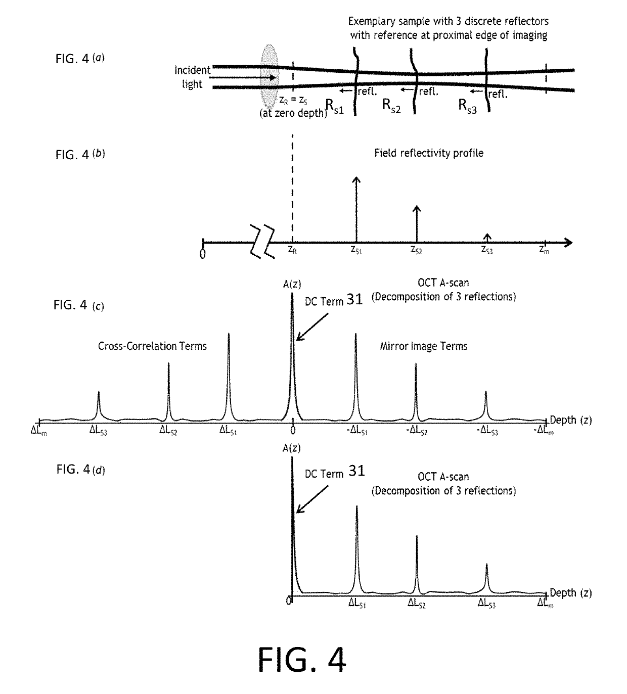
[0066]FIGS. 6(a)-6(d) show an exemplary sample reflectivity profile having three discrete reflectors with the reference reflection at t...

second embodiment

[0068]Another method for reducing crosstalk involves placing the reference arm (see ZR) at a shorter distance than the proximal edge of the image FOV, (see FIGS. 9(a)-10(d)), in which case, even though crosstalk noise wraps about DC it no longer lands in the desired imaging range (see e.g., FIG. 10(c)). For instance, a multimodality OCT system employing a double clad fiber segment where the reference reflection for the OCT modality is positioned at a shorter optical path length than the proximal edge of the FOV (i.e., the optical path length of the reference reflection is shorter than the first desired sample reflection such that crosstalk noise wraps about DC and is no longer in the desired imaging range) may be used as one example of the second embodiment.

[0069]FIGS. 9(a)-(d) show an exemplary sample reflectivity profile having three discrete reflectors with the reference reflection shorter than the desired start of the image FOV (see FIGS. 9(a)-9(b)), an A-scan from the Fourier d...


PUM


Abstract

One or more devices, systems, methods and storage mediums for performing optical coherence tomography (OCT) while reducing and / or eliminating crosstalk noise are provided. Examples of such applications include imaging, evaluating and diagnosing biological objects, such as, but not limited to, for Gastro-intestinal, cardio and / or ophthalmic applications, and being obtained via one or more optical instruments, such as, but not limited to, optical probes, catheters, capsules and needles (e.g., a biopsy needle). Preferably, the OCT devices, systems methods and storage mediums include or involve a method, such as, but not limited to, a complex conjugate method or a shift method, for handling the crosstalk noise in a way to mitigate or eliminate the noise from an image field of view. For example, a reference reflection or reference arm may be positioned or re-positioned in the image field of view at different locations depending on the crosstalk noise mitigation method being employed.

Description

FIELD OF THE INVENTION[0001]The present disclosure relates generally to the field of optical imaging and more particularly to optical coherence tomography (OCT) devices, systems, methods and storage mediums using crosstalk elimination or mitigation. Examples of such applications include imaging, evaluating and diagnosing biological objects, such as, but not limited to, for gastro-intestinal, cardio and / or ophthalmic applications, and being obtained via one or more optical instruments, such as, but not limited to, one or more optical probes, one or more catheters, one or more endoscopes, one or more capsules, and one or more needles (e.g., a biopsy needle).BACKGROUND OF THE INVENTION[0002]Optical coherence tomography (OCT) is a technique for obtaining high resolution cross-sectional images of tissues or materials, and enables real time visualization. The aim of the OCT techniques is to measure the time delay of light by using an interference optical system or interferometry, such as ...

Claims


Application Information

Patent Timeline
Patent Type & Authority Patents(United States)
IPC IPC(8): A61B5/00G01B9/02G01N21/47
CPCG01B9/02091A61B5/0066G01B9/02001G01B9/02064G01N21/4795G01N2021/4797
Inventor ELMAANAOUI, BADR
Owner CANON USA
Why Eureka
Try Eureka