LED insect light trap with light transmissive glue board

a technology of insect light and glue board, which is applied in the field of insect light traps, can solve the problems of environmental pollution, health concerns, and disposal of such light sources, and achieve the effects of improving insect attraction, reducing energy consumption, and improving insect attraction

Active Publication Date: 2019-06-25
GARDNER MFG CO INC
View PDF21 Cites 16 Cited by
  • Summary
  • Abstract
  • Description
  • Claims
  • Application Information

AI Technical Summary

Benefits of technology

[0009]The housing is adapted to hold the electronic circuit and the glue board so that the front side of the glue board coated with the adhesive faces away from the electronic circuit and the light-emitting diodes emit UV light through the glue board. The housing also has a front panel including openings defined by closed sections having edges. The openings permit flying insects to enter the trap through such openings. The openings also permit the adhesive layer of the glue board to be viewed through such openings by flying insects. The closed sections are adapted to cause at least some of the light from the light-emitting diodes reaching the closed sections to bounce off the closed sections and on to the adhesive layer coating a portion of the front surface of the glue board. The closed sections also serve to at least partially mask from the view of humans standing or sitting in the room insects stuck to the glue board.
[0012]Also, the light-emitting diodes of the circuit may be arranged in a pattern. That pattern may comprise at least two rows of light-emitting diodes. When the glue board has perforations, those perforations may be arranged in the same pattern as the pattern of the light-emitting diodes. The light-emitting diodes may also be adapted to emit light in both the ultraviolet and visible light ranges. The electrical circuit comprising the light-emitting diodes may also be designed to cause the light-emitting diodes to selectively dim and brighten or cycle on and off to increase insect attraction.
[0015]The glue board may be UV transparent or UV translucent. Alternatively, the glue board may be generally UV opaque, but have perforations which enable UV light to pass through the glue board. If generally UV opaque with perforations, the glue board may be colored black to partially mask from the human eye any insects stuck to the glue board. Otherwise, humans could see the insects due to the presence of ambient light even though humans cannot see the UV light generated by the light-emitting diodes. The adhesive may be selected to provide a glossy surface to increase insect attraction or to provide a matte surface to better hide the captured insects from the view of humans. The substrate or adhesive may be smooth to cause the UV light to bounce off the glue board in a specular manner, or may be textured to cause the UV light to bounce off the glue board in a more diffuse manner.
[0016]The housing may have an opening that permits the glue board to be quickly and easily removed and replaced without removing any portion of the housing. Also, the edges of the openings in the front of the housing may be adapted to be illuminated by the light-emitting diodes to essentially frame the openings with insect attractant light.

Problems solved by technology

However, energy consumption by such light sources and disposal of such light sources create environmental issues.
Health concerns can also arise if the fluorescent tube breaks and its contents are inhaled or ingested.
These, however, are entirely unsuitable for restaurants and other areas where food is prepared or served due to splatter of bug parts.
Second, various poisons have been employed, but the use of a poison is unacceptable where young children are present who might ingest the poison.
Third, various mechanisms have been employed to move the insects into chambers from which the insect cannot escape.
Glue boards are generally safe, but a glue board coated with flying insects is generally unsightly and unpleasant to look at.
Also, if the light source is any distance from the glue board, insects attracted to the light source may never come into contact with the glue board and, thus, may fly away without being captured.

Method used


Image

  • LED insect light trap with light transmissive glue board
  • LED insect light trap with light transmissive glue board
  • LED insect light trap with light transmissive glue board

Examples


Embodiment Construction

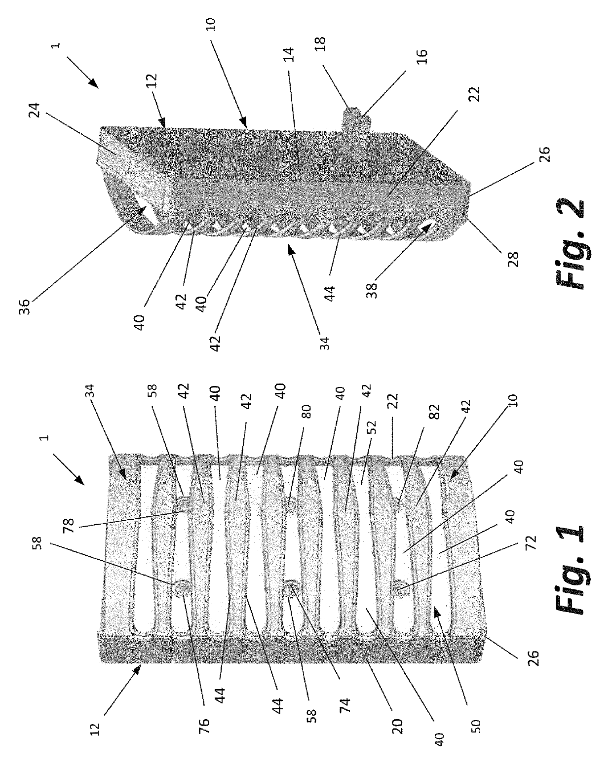
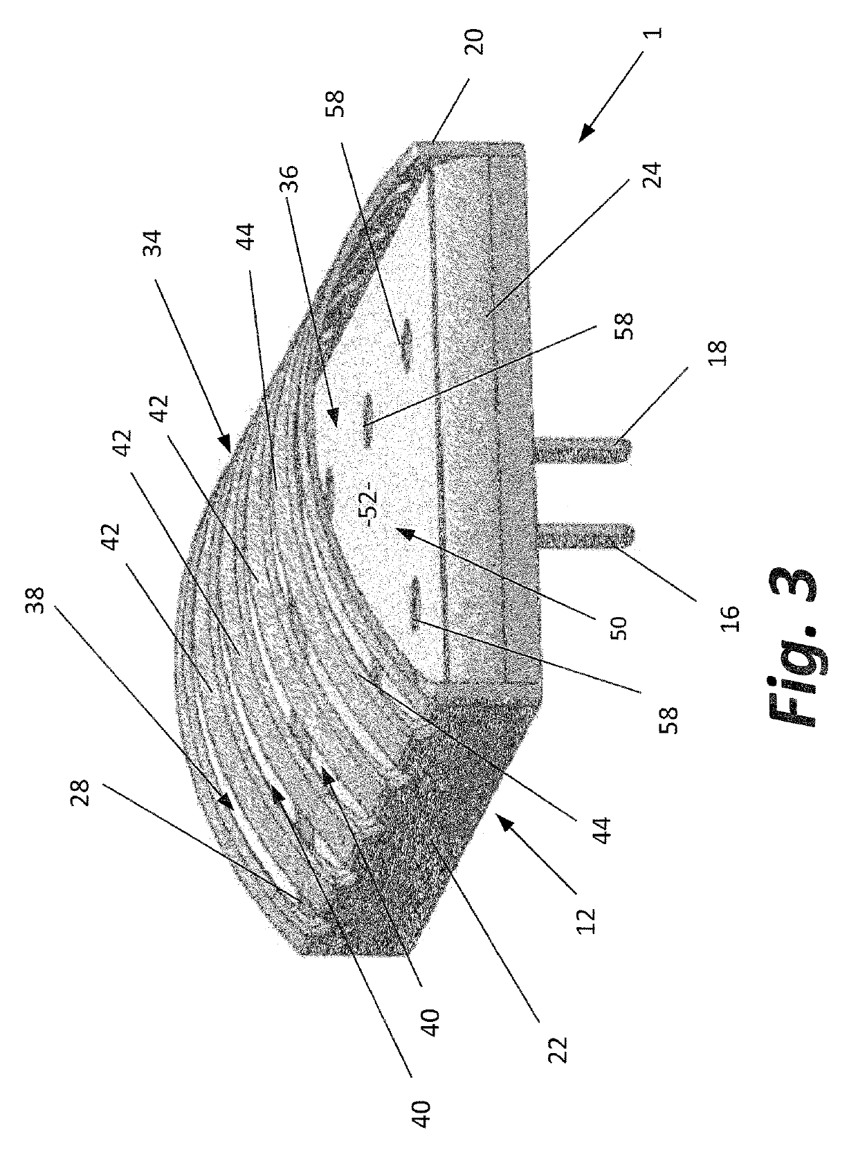
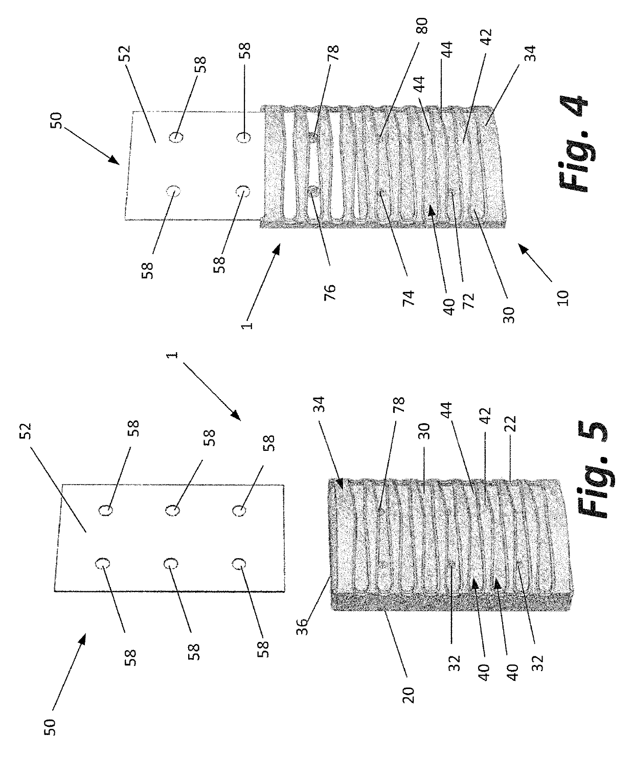
[0027]This description of the preferred embodiment is intended to be read in connection with the accompanying drawings, which are to be considered part of the entire written description of this invention. In the description, relative terms such as “lower”, “upper”, “horizontal”, “vertical”, “above”, “below”, “up”, “down”, “top” and “bottom”, “under”, as well as derivatives thereof (e.g., “horizontally”, “downwardly”, “upwardly”, “underside”, etc.) should be construed to refer to the orientation as then described or as shown in the drawings under discussion. These relative terms are for convenience of description and do not require that the apparatus be constructed or operated in a particular orientation. Terms such as “connected”, “connecting”, “attached”, “attaching”, “joined”, and “joining” are used interchangeably and refer to one structure or surface being secured to another structure or surface or integrally fabricated in one piece unless expressly described otherwise.

[0028]The...


PUM


Abstract

Insect capture is improved by providing a glue board having an adhesive coating on its front surface and forming a pattern of insect attractant UV light on that front surface. That pattern includes areas of bright UV light generated by light-emitting diodes that generate light at different wavelengths behind and visible through the glue board by flying insects, dimmer areas of light generated by said light emitting diodes that bounces off other portions of the device onto the glue board, and areas of shadow on the glue board where no or little light from said light-emitting diodes is present.

Description

CROSS-REFERENCED TO RELATED APPLICATIONS[0001]This application is a continuation-in-part of application Ser. No. 15 / 132,558, filed Apr. 19, 2016, entitled “INSECT LIGHT TRAP WITH LIGHT TRANSMISSIVE GLUE BOARD”, which is deemed incorporated herein by reference in its entirety.STATEMENT REGARDING FEDERALLY SPONSORED RESEARCH OR DEVELOPMENT[0002]Not applicable.BACKGROUND OF THE INVENTIONI. Field of the Invention[0003]The present invention relates generally to insect traps. More specifically, the present invention relates to improvements to insect traps employing a light source as an insect attractant and a glue board as an insect capture device.II. Discussion of Related Art[0004]Those skilled in the art know that light provides an effective insect attractant and that light in the ultraviolet (“UV”) range of the light spectrum is particularly attractive to many flying insects. UV light is light having a wave length generally in the range of 100 to 400 nanometers.[0005]Based on this phen...

Claims


Application Information

Patent Timeline
Patent Type & Authority Patents(United States)
IPC IPC(8): A01M1/04A01M1/14A01M1/10H05B33/08H05B44/00
CPCA01M1/145A01M1/106H05B33/0815H05B45/20
Inventor STUDER, BRUCE R.JONES, TIMOTHY M.
Owner GARDNER MFG CO INC
Why Eureka
Try Eureka