Buckle

a technology of buckles and buckles, applied in the field of buckles, can solve the problems of poor product durability, buckles with a traditional structure often getting broken, and general structure buckles that do not meet special use requirements, and achieve the effects of simple structure, reasonable design, and realizing the dispersion of strength

Active Publication Date: 2019-06-25
CHEN SILONG
View PDF8 Cites 0 Cited by
  • Summary
  • Abstract
  • Description
  • Claims
  • Application Information

AI Technical Summary

Benefits of technology

[0006]Compared with the prior art, the buckle in the present invention possesses advantages of a simple structure as well as a reasonable design, and may realize the dispersion of the strength by utilizing the special structure of the lock core, in which case, the structural strength gets ensured, and at the same time the buckle may be kept light-weighted, and thus the buckle is suitable for the pet industry.

Problems solved by technology

Because of the different using requirements of the buckle in different industries, buckles with a general structure usually may not meet some special using demands.
More specifically, because of the pet hyperactivity, the buckle's lock would be impacted by an extremely huge instantaneous impact, and the buckle with a traditional structure would often get broken after getting used for a period of time, involving poor product durability.
Although some buckles for pets are provided with an all-metal structure, due to the large weight of the metal, as well as its traditional structure, after being used for a period time, it will be inconvenient to pressure to open the buckle.
In summary, the traditional buckle may not properly meet the pet industry's using demands on the buckle, and there is an urgent need of a buckle with a lightweight and high structural strength, and may open conveniently after an impact.

Method used


Image

  • Buckle
  • Buckle

Examples


Embodiment Construction

[0011]The present invention will hereinafter be described in detail with reference to an exemplary embodiment, for the purpose of further understanding the present invention.

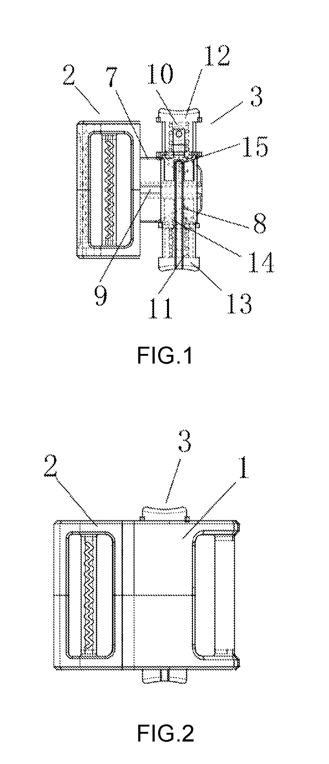
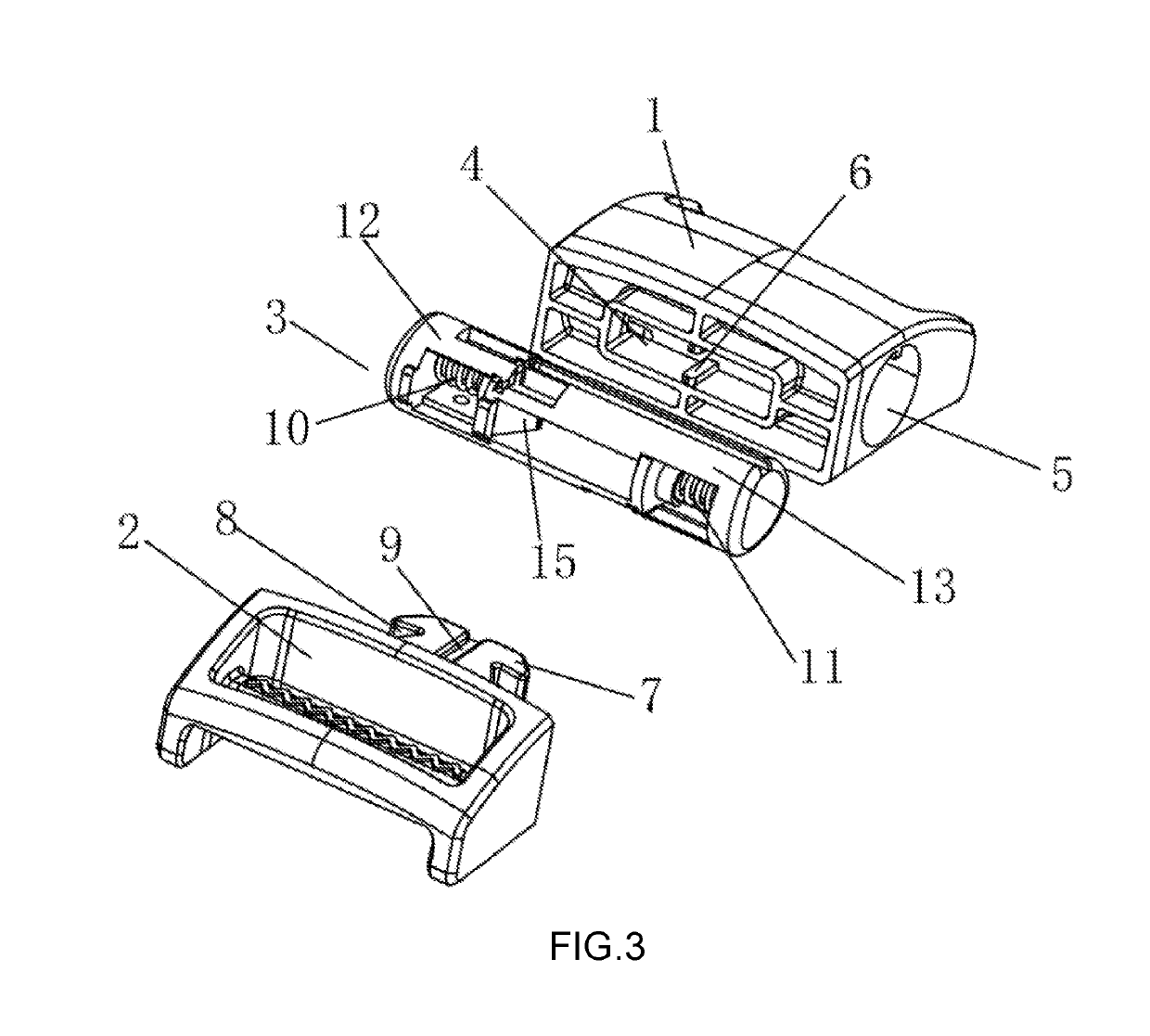
[0012]Referring to FIGS. 1-3, the buckle in an embodiment of the invention includes a plastic shell 1, an inserting element 2, and a lock core 3. A horizontal socket 4 is configured on the plastic shell 1 for fitting with the inserting element 2, and a cylindrical mounting slot 5 is configured on the shell 1 for the installation of the lock core 3. The cylindrical groove 5 is communicated with the horizontal socket 4. The horizontal socket 4 is provided with a guiding block 6, and the inserting element 2 is provided with an inserting piece 7 for inserting into the horizontal socket 4 to engage with the lock core 3, with two triangular notches 8 symmetrically formed on the inserting piece 7. The inserting piece 7 of the inserting element 2 is provided with a guiding groove 9 which cooperates with the guiding bloc...


PUM


Abstract

An improved buckle includes a plastic shell, an inserting element, and a lock core. A horizontal socket fitting with the inserting element and a cylindrical mounting slot for mounting the lock core are formed on the plastic shell, the cylindrical mounting slot communicating with the horizontal socket. The horizontal socket includes a guiding block, and the inserting element includes an inserting piece for inserting into the horizontal socket to cooperate with the lock core, with two triangular notches symmetrically and a guiding groove cooperating with the guiding block formed thereon. The buckle has advantages of a simple structure and a reasonable design, and may realize the dispersion of the strength by utilizing the special structure of the lock core, so the structural strength gets ensured, and meanwhile the buckle may be kept light-weighted, and thus the buckle is suitable for the pet industry.

Description

BACKGROUND OF THE INVENTION[0001]The present invention relates to a buckle, specifically to a type of improved buckle achieving a better locking stability by structural modifications.[0002]As a locking device, buckles are widely used. Because of the different using requirements of the buckle in different industries, buckles with a general structure usually may not meet some special using demands. Specifically, in the pet supplies industry, the buckle is mostly applied on horseback pet straps, or traction pet straps, pet bags, or pet retractors, due to the particularity of the industry, there are extremely high requirements on the buckle's impact resistance. More specifically, because of the pet hyperactivity, the buckle's lock would be impacted by an extremely huge instantaneous impact, and the buckle with a traditional structure would often get broken after getting used for a period of time, involving poor product durability. Although some buckles for pets are provided with an all-...

Claims


Application Information

Patent Timeline
Patent Type & Authority Patents(United States)
IPC IPC(8): A44B11/02A44B11/25A01K27/00
CPCA44B11/2592A44B11/02A01K27/001A44B11/266
Inventor CHEN, SILONG
Owner CHEN SILONG
Why Eureka
Try Eureka