Energy-saving traction-type elevator

a technology of traction-type elevators and traction-type elevators, which is applied in the direction of elevators, mine lifts, sustainable buildings, etc., can solve the problems of energy waste, difficulty in elevators, and drive moment and power was

Active Publication Date: 2019-06-25
HANGZHOU HANGYAN ENVIRONMENT TECH CO LTD +1
View PDF13 Cites 3 Cited by
  • Summary
  • Abstract
  • Description
  • Claims
  • Application Information

AI Technical Summary

Benefits of technology

[0033]The present invention has the following beneficial effects: by using the principle of moment balancing and adding the independent balancing counterbalance for elevator to realize the smart counterbalancing of the elevator, the elevator reaches a relative balance status, thereby reducing the traction moment and power of the traction machine, when the potential energy of the balancing counterbalance of the elevator builds up a higher position, the power-generating electric motor can perform centralized power generation, aiding energy recovery and use; the effects of effective energy-saving and extended service life of the traction machine are achieved by storing, releasing and recovering the potential energy.

Problems solved by technology

Usually, the ratio of the counterweight to the car weight is 1.5:1, and the load varies frequently, so it is difficult to the elevator to get in the ideal status.
On the contrary, if the counterbalance unit and the car have a weight difference, the working of the elevator inevitably results in accumulation and release of the mechanical potential energy, thereby causing waste of energy.
The prior art has at least the following problems: the existing variable counterbalancing elevator can reduce the drive moment and power of the traction machine and fulfill the aim of saving energy and improving the service life of the traction machine; however, the assembling and dismantling of the counterbalance unit inevitably results in power loss; meanwhile, if the load changes dramatically, many counterbalance units are required to be assembled and dismantled, thereby wasting time.

Method used


Image

  • Energy-saving traction-type elevator
  • Energy-saving traction-type elevator
  • Energy-saving traction-type elevator

Examples


Embodiment Construction

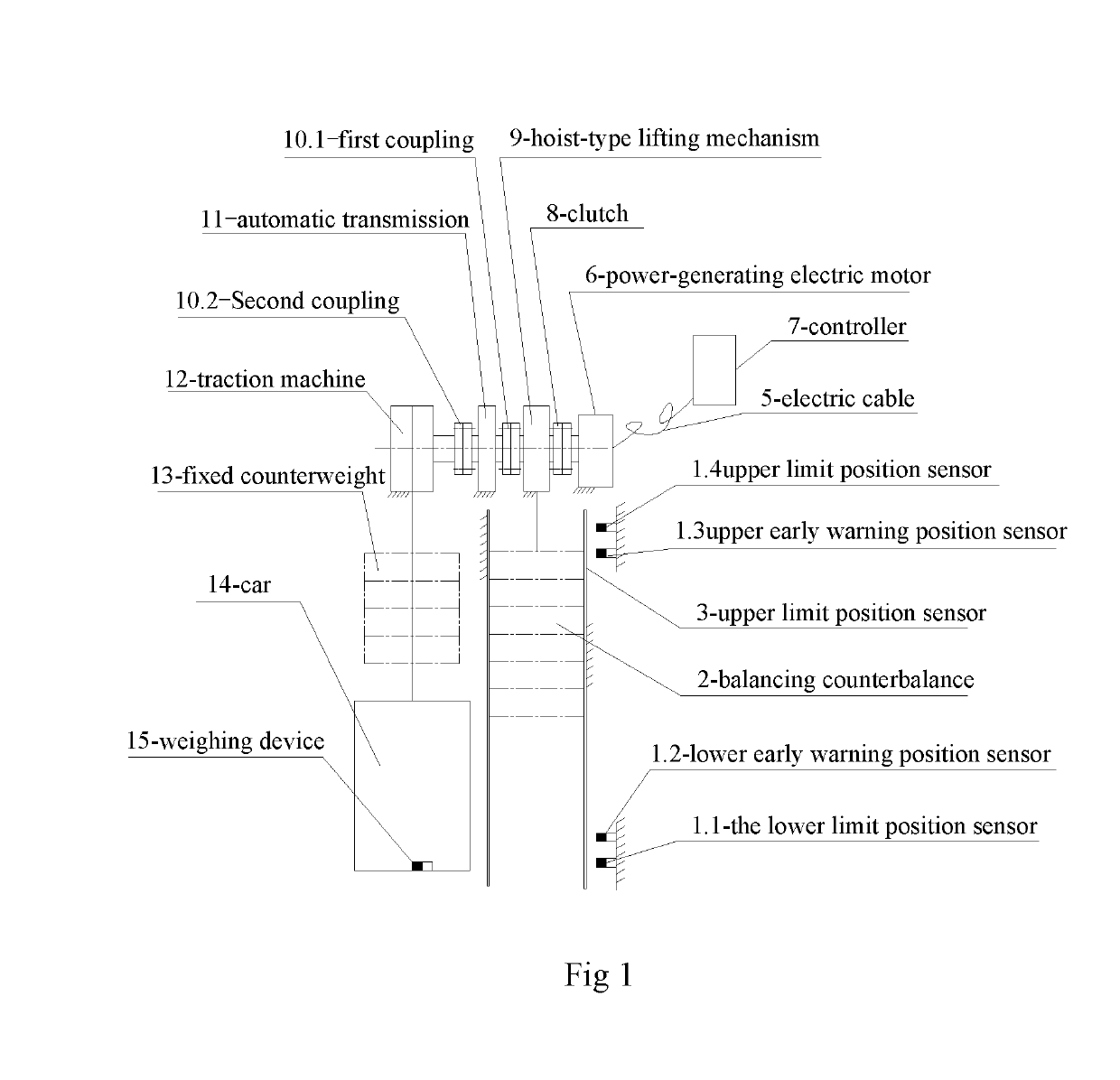
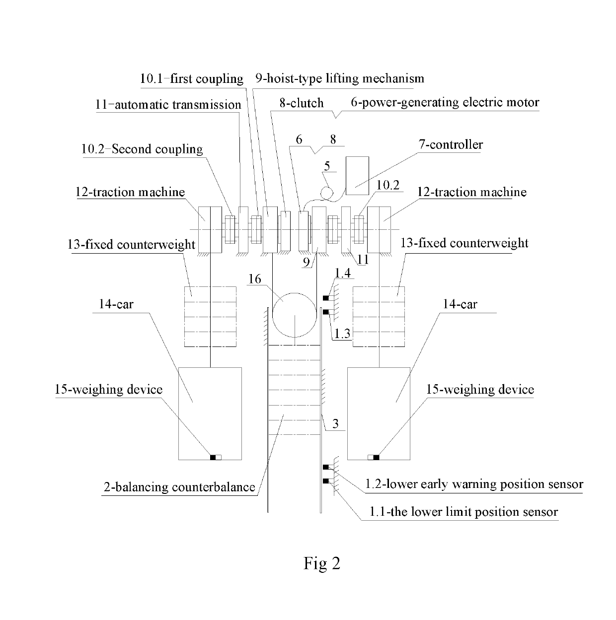
[0037]The present invention is described in detail with reference to the attached drawings. As shown in FIGS. 1 and 2, an elevator includes at least one counterbalance unit; each counterbalance unit includes a traction machine 12, an automatic transmission 11, a hoist-type lifting mechanism 9, a power-generating electric motor 6, a controller 7 which are provided in a machine room and a car 14, a fixed counterweight 13 and a balancing counterbalance 2 which are provided in an elevator shaft;

[0038]an output shaft of said traction machine is connected with an input of the automatic transmission 11; an output shaft of the automatic transmission 1 is connected with one end of a rotating shaft of the hoist-type lifting mechanism 9 through a first coupling 10.1; the other end of the rotating shaft of the hoist-type lifting mechanism 9 is connected with a motor shaft of the power-generating electric motor 6;

[0039]the car 14 and the fixed counterweight 13 are suspended on the traction machi...


PUM


Abstract

An energy-saving traction-type elevator and an energy-saving method therefor are presented. The traction-type elevator includes at least one counterbalance unit, each counterbalance unit comprising a traction machine. The traction-type elevator further includes an automatic transmission, a hoist-type lifting mechanism, a power-generating electric motor, and a controller provided in a machine room, and a car, a fixed counterweight and a balancing counterbalance provided in an elevator shaft. The energy-saving method applies the principle of moment balance, whereby adding a separate elevator balancing counterbalance to achieve intelligent counterbalancing of the elevator so that the elevator achieves relative balance, thereby reducing the traction moment and rate of work of the traction machine. When the potential energy of the elevator balancing counter-balance builds up to a high position, the power-generating electric motor can perform centralized power generation, aiding in energy recovery and use.

Description

CROSS REFERENCE TO RELATED APPLICATIONS[0001]The present application is the US national stage of International Patent Application PCT / CN2014 / 093419 filed on Dec. 10, 2014, which, in turn, claims priority to Chinese Patent Application CN 201310695900.8 filed on Dec. 17, 2013.TECHNICAL FIELD[0002]The present invention relates to an energy-saving traction-type elevator and an energy-saving method thereof, belonging to the field of elevator energy saving.DESCRIPTION OF THE RELATED ART[0003]It is well known that, as elevators are a kind of a vertical transport tool, the car (load) and counterweight both have potential energy features. During working, an elevator carries approximately the same mass up and downward, and in terms of energy conservation, the power loss of the elevator only meets friction heating. In terms of mechanical energy, the elevator is in an ideal status if the elevator car (load) is equal to a counterweight. Usually, the ratio of the counterweight to the car weight i...

Claims


Application Information

Patent Timeline
Patent Type & Authority Patents(United States)
IPC IPC(8): B66B1/34B66B11/04B66B17/12B66B1/28B66B5/00B66B9/00
CPCB66B1/28B66B5/0018B66B9/00B66B11/0492B66B17/12B66B11/043Y02B50/144B66B1/302Y02B50/00
Inventor YE, RONGWEIWANG, XIUXIULV, YANBINHE, DAZHI
Owner HANGZHOU HANGYAN ENVIRONMENT TECH CO LTD
Why Eureka
Try Eureka