Fan unit, and assembling and removing method thereof

a technology of fan unit and assembly method, which is applied in the direction of non-positive displacement fluid engine, pump components, liquid fuel engine components, etc., can solve the problems of not being able to quickly maintain, remove, and over-design of the fan unit, and achieve the effect of convenient operation, simple removal process and convenient operation

Active Publication Date: 2019-06-25
INVENTEC PUDONG TECH CORPOARTION +1
View PDF9 Cites 2 Cited by
  • Summary
  • Abstract
  • Description
  • Claims
  • Application Information

AI Technical Summary

Benefits of technology

[0017]Compared to the prior art, according to the technique related to the structure, the assembling method and the removing method of the fan unit disclosed in the present invention, it can be known that the technique of the present invention can perform the following beneficial effects. The fan unit of the present invention can assemble the fan unit in the electronic device quickly through the handle connected to the fixture. Thus, the fan assembling process becomes easy, convenience, and quick. Simultaneously, when the fan unit of the present invention needs to be removed, the handle can be operated to move pivotally to remove the fan unit form the electronic device quickly, and the removing process is simple, and can be operated conveniently.
[0018]The fan unit of the present invention can achieve the pivotal position of the handle to be operated conveniently through the engaging connection between the through hole of the fixture and the flexible bolt of the handle. When the handle is located in the first position, the flexible bolt is fixed with the electronic device directly, thus the fan unit can be assembled into the electronic device independently without assembling the fan bracket. Therefore, when the fan needs to be replaced, it is unnecessary to remove the fan bracket, so as to make the removing process of the fan become easier. Simultaneously, the manufacturing cost of the electronic device can be reduced.
[0019]An cutout restricted the handle in the second position is formed on the bending line of the fixture in the present invention. Compare to the means of applying a protruding structure for stopping in prior art, the structure of the present invention is more simple, and the manufacturing cost is less. The fixture of the present invention is configured with the guiding structure which is applied to guide the fan unit move along the guiding direction. The design of the guiding structure makes the fan unit be assembled fast and accurately. The second avoidance space accommodated the second wire coupled between the fan indicator light and the fan is formed in a front portion of the fixture of the present invention. This design can expand the assembling space of the second wire to make the fan indicator light be assembled smoothly.

Problems solved by technology

However, the above design of the fan unit can't be assembled, removed, and maintained quickly.

Method used


Image

  • Fan unit, and assembling and removing method thereof
  • Fan unit, and assembling and removing method thereof
  • Fan unit, and assembling and removing method thereof

Examples


Embodiment Construction

[0030]The invention disclosed herein is directed to a historical work parameter. In the following description, numerous details are set forth in order to provide a thorough understanding of the present invention. It will be appreciated by one skilled in the art that variations of these specific details are possible while still achieving the results of the present invention. In other instance, well-known components are not described in detail in order not to unnecessarily obscure the present invention.

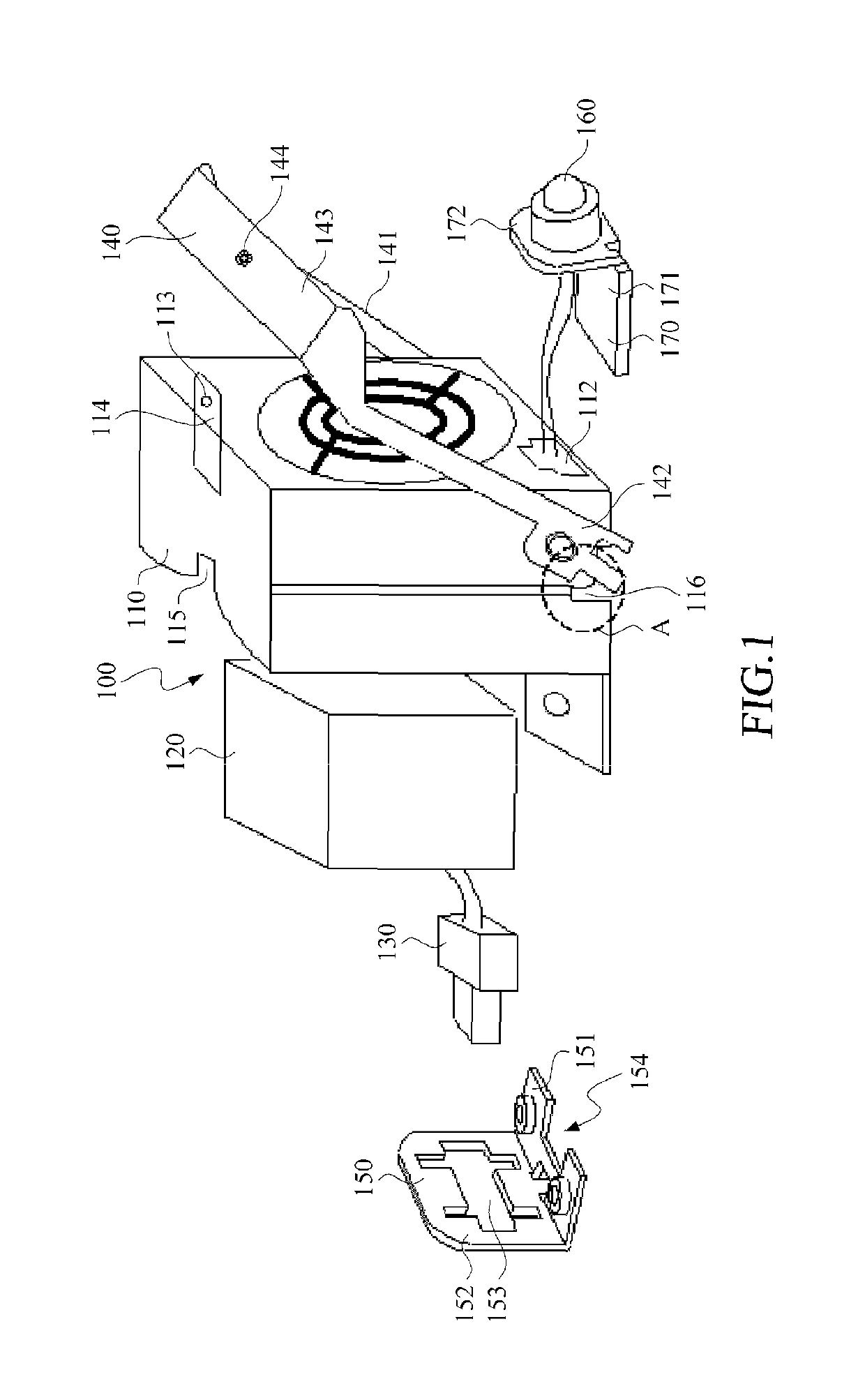
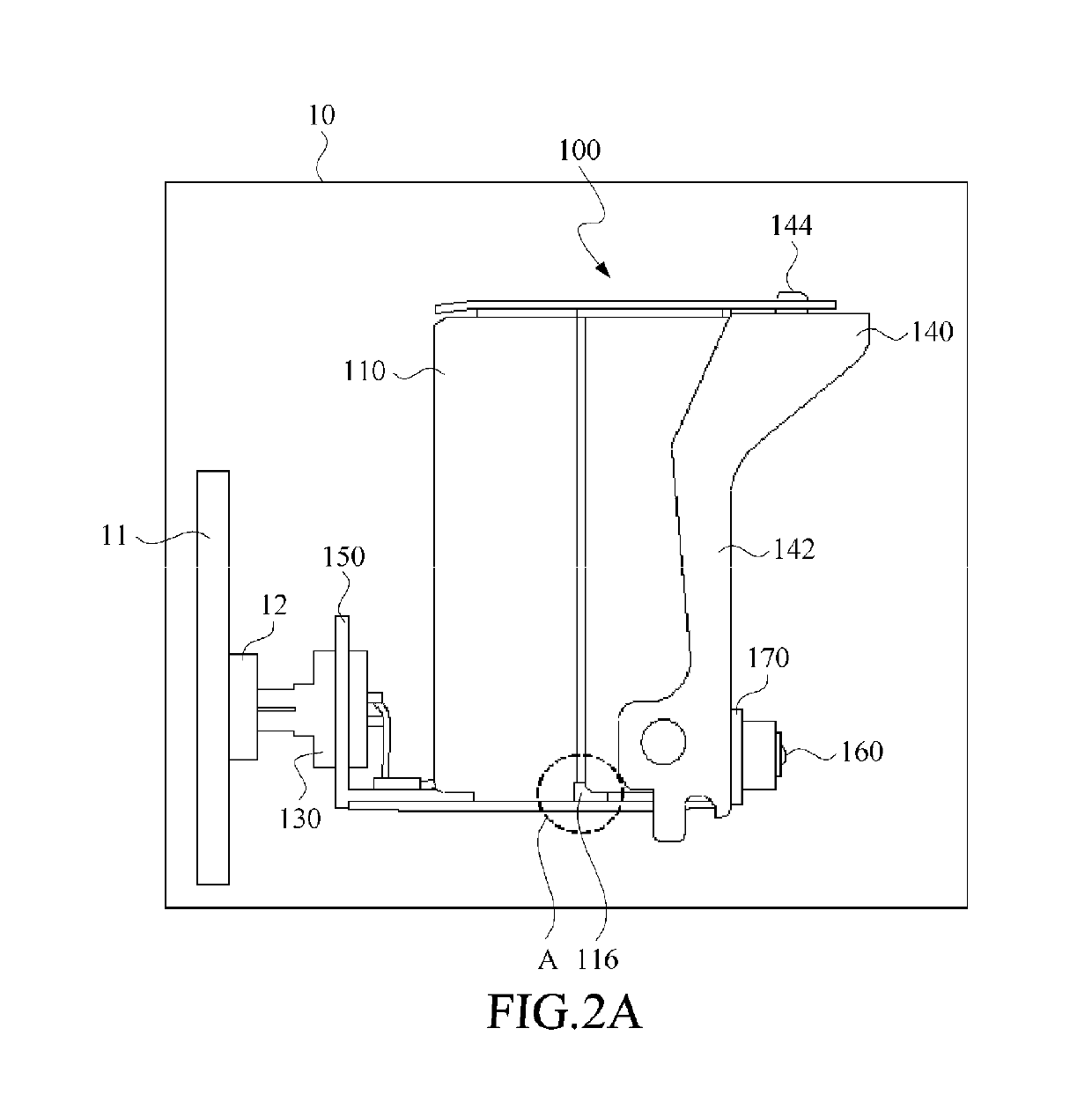
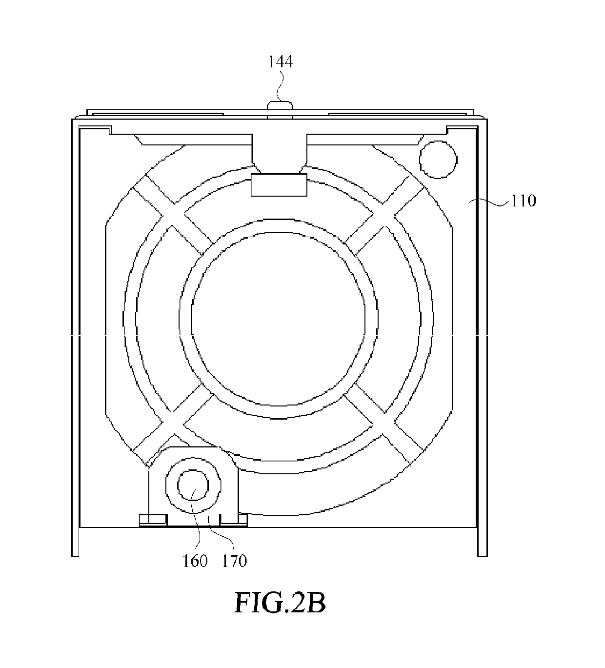
[0031]FIG. 1 is an exploded view illustrating the fan unit according to one preferred embodiment of the present invention. FIG. 2A is a side view illustrating the fan unit being assembled and located in a first position depicted in FIG. 1. FIG. 2B is a front view illustrating the fan unit being assembled and located in a first position depicted in FIG. 1. FIG. 2C is a side view illustrating the fan unit being assembled and located in a second position depicted in FIG. 1.

[0032]Referring ...


PUM


Abstract

The invention relates to a method for assembling a fan unit into an electronic device and removing therefrom. The electronic device has a first connector. The fan unit includes a fixture, a fan, a second connector and a handle. The fan is assembled into the fixture and electrically connected to the second connector. The handle is pivotally connected to the fixture and operable to be pivotally moved between a first position and a second position of the fixture. When the handle is operated to move to the first position, the fixture is pushed to approach to the first connector, so as to so as make the second connector connect to the first connector in mechanical and electrical. When the handle is operated to move to the second position, the fixture is pulled out by the handle, so as to make the second connector disconnected to the first connector.

Description

BACKGROUND OF INVENTION[0001]1. Field of the Invention[0002]The present invention relates to a fan unit adapt for an electronic device and assembling and removing method thereof.[0003]2. Description of the Prior Art[0004]In general, the electronic device, such as a server, is usually configured with a fan module for heat dissipation, and then the heat generated from the internal circuit components of the electronic device in actual operation is dissipated through airflow produced by the fan module. Through this means, it is able to prevent the internal circuit elements of the electronic device from damage caused by overheating. However, the current fan module is designed with the function of Hot-Plug to avoid interrupting operation of the electronic device when replacing the fan module.[0005]Currently, the fan module generally includes a fan bracket, and at least one fan unit with hot-plug function is disposed in the interior of the fan bracket. The fan unit is latched in the fan br...

Claims


Application Information

Patent Timeline
Patent Type & Authority Patents(United States)
IPC IPC(8): F04D29/60F04D29/58F04D29/52F04D29/64
CPCF04D29/601F04D29/646F04D29/584F04D29/522
Inventor ZHU, HUIWANG, JIA-BIN
Owner INVENTEC PUDONG TECH CORPOARTION
Why Eureka
Try Eureka