Environmental testing device

a technology for environmental testing and equipment, applied in the direction of fluid tightness measurement, lighting and heating equipment, instruments, etc., can solve the problems of difficult control of a test temperature down to a significantly low temperature zone, and cannot be said, so as to achieve stable temperature control, easy control, and stable refrigerating capacity output

Active Publication Date: 2019-06-25
SHINWA CONTROLS
View PDF28 Cites 1 Cited by
  • Summary
  • Abstract
  • Description
  • Claims
  • Application Information

AI Technical Summary

Benefits of technology

[0007]The present invention has been made in view of the above circumstances. The object of the present invention is to provide an environmental testing apparatus capable of sufficiently ensuring a space in a chamber in which an object to be tested is accommodated, and of controlling a temperature in the space within a broad temperature zone, in particular, down to a significantly low-temperature zone, whereby it is possible to subject an object to be tested to an environmental testing sufficiently considering various environments.
[0028]According to the present invention, it is possible to sufficiently ensure a space in the chamber in which an object to be tested is accommodated, and to control a temperature in the space within a broad temperature zone, in particular, down to a significantly low temperature zone, whereby it is possible to subject an object to be tested to environmental tests sufficiently considering various environments.

Problems solved by technology

However, it cannot be said that the temperature zone of between −40° C. and 85° C., within which an environmental test can be carried out, is sufficient enough, in consideration of environmental tests conceiving various environments.
However, in a testing device of such a kind, when a space in a chamber, whose temperature is to be controlled is enlarged, there occurs a problem in that control of a test temperature down to a significantly low temperature zone becomes difficult.

Method used


Image

  • Environmental testing device
  • Environmental testing device
  • Environmental testing device

Examples


« first embodiment

[0040]«First Embodiment»

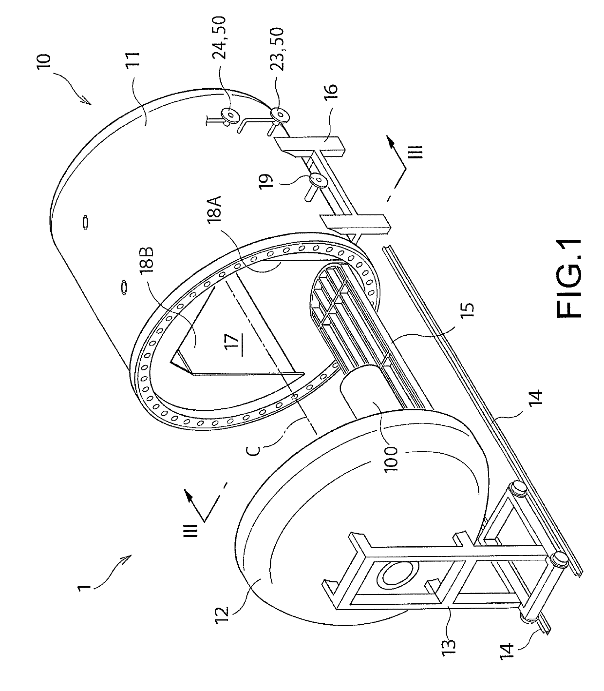
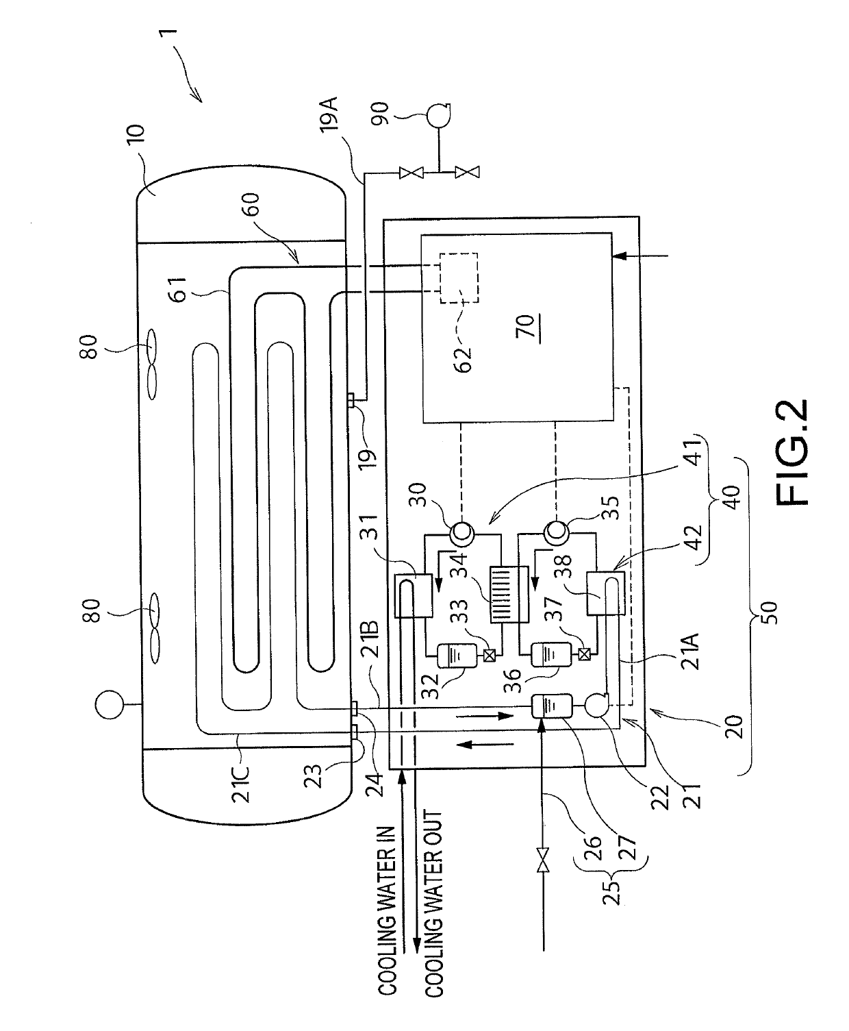
[0041]FIG. 1 is a perspective view of an environmental testing apparatus according to a first embodiment of the present invention. FIG. 2 is a view showing a circuit structure of the environmental testing apparatus shown in FIG. 1. As shown in FIGS. 1 and 2, the environmental testing apparatus 1 according to this embodiment includes a chamber 10 that accommodates an object 100 to be tested, such as a hydrogen tank, a cooling unit 50, a heating unit 60, and a control apparatus 70. In FIG. 1, the chamber 10 and the cooling unit 50 are only partially shown, for the sake of convenience of explanation.

[0042]As shown in FIG. 1, the chamber 10 in this embodiment has a cylindrical body part 11 with a bottom, and a discoid lid part 12 capable of opening and closing an opening of the body part 11. FIG. 1 shows an opened state of the chamber 10, in which the body part 11 is opened by the lid part 12. By closing the body part 11 with the lid part 12, the chamber 10 becom...


PUM

PropertyMeasurementUnit
temperatureaaaaaaaaaa
internal volumeaaaaaaaaaa

Abstract

An environmental testing apparatus includes a chamber, a cooling unit including a cooling apparatus of a brine that cools the inside of the chamber, a heating unit and a control apparatus. The cooling apparatus includes: a high temperature side cooling circuit including a high temperature side compressor, condenser, high temperature side expansion valve and cascade condenser connected in this order to circulate a high temperature side heating medium; and a low temperature side cooling circuit including a low temperature side compressor, cascade condenser, low temperature side expansion valve and evaporator connected in this order to circulate a low temperature side heating medium. The low temperature side heating medium is cooled by the high temperature side heating medium in the cascade condenser, while the brine is cooled by the low temperature side heating medium in the evaporator. The control apparatus controls a temperature inside the chamber to between −67.5° C. and 127.5° C.

Description

FIELD OF THE INVENTION[0001]The present invention relates to an environmental testing apparatus for subjecting an object to be tested, such as a hydrogen tank, to an environmental testing in a low temperature zone and a high temperature zone.BACKGROUND ART[0002]As a method of filling a hydrogen tank of a fuel cell vehicle with hydrogen as fuel, there are known a method of compressing hydrogen at a high pressure and filling the hydrogen into a hydrogen tank, a method of liquefying hydrogen and filling the hydrogen into a hydrogen tank, and the like. When hydrogen is compressed at a high pressure and is filled into a hydrogen tank, the higher the pressure at which the hydrogen is compressed is, the more a filling amount of hydrogen can be increased, which can elongate a cruising distance of a fuel cell vehicle. On the other hand, as a pressure of hydrogen when it is supplied into a hydrogen tank and a pressure of the hydrogen filled therein increase, the hydrogen is more likely to lea...

Claims


Application Information

Patent Timeline
Patent Type & Authority Patents(United States)
IPC IPC(8): G01M3/00G01N17/00F25B7/00
CPCG01M3/002G01N17/00F25B7/00F25B2400/06F25B5/04F25B25/005F25B40/00F25B49/02F25B2339/047F25B2400/0409F25B2400/061F25B2600/0251F25B2600/0261F25B2600/13F25B2600/2501F25B2600/2509F25B2700/1933F25B2700/21151Y02B30/70F25B41/20G01N17/002G01N17/006G01N3/60G01N2203/0222
Inventor FURUMOTO, HIDEAKIITO, TOMOAKI
Owner SHINWA CONTROLS
Why Eureka
Try Eureka