Clamp apparatus

a technology of clamping and clamping rods, which is applied in the direction of clamps, manufacturing tools, and vices, etc., can solve the problems of affecting the rotational operation of the clamping rods, affecting the removal of spatter, so as to achieve the elimination of spatter, easy and reliable removal, and short time

Active Publication Date: 2019-07-02
SMC CORP
View PDF6 Cites 0 Cited by
  • Summary
  • Abstract
  • Description
  • Claims
  • Application Information

AI Technical Summary

Benefits of technology

[0005]A general object of the present invention is to provide a clamp apparatus, which is capable of easily and reliably removing to the exterior spatter that has invaded into the interior of the body.
[0014]Accordingly, by detaching the detachable cover from the body, and removing the unloading tray on which spatter is deposited, the spatter can easily and reliably be taken out to the exterior of the body and eliminated. As a result, malfunctioning of the drive unit, the driving force transmission mechanism, and the clamp arms due to deposit of spatter thereon can be prevented, clamping of workpieces can be carried out smoothly at all times, and elimination of spatter can be carried out reliably in a short period of time. Therefore, ease of maintenance on the clamp apparatus can be enhanced.

Problems solved by technology

Thus, for example, displacement of the base, which is displaced in a downward direction, is hindered, and rotational operation of the clamp arms is interfered with.
However, spatter frequently becomes fixedly attached to the body, and elimination of such spatter is extremely complicated.

Method used


Image

  • Clamp apparatus
  • Clamp apparatus
  • Clamp apparatus

Examples


first embodiment

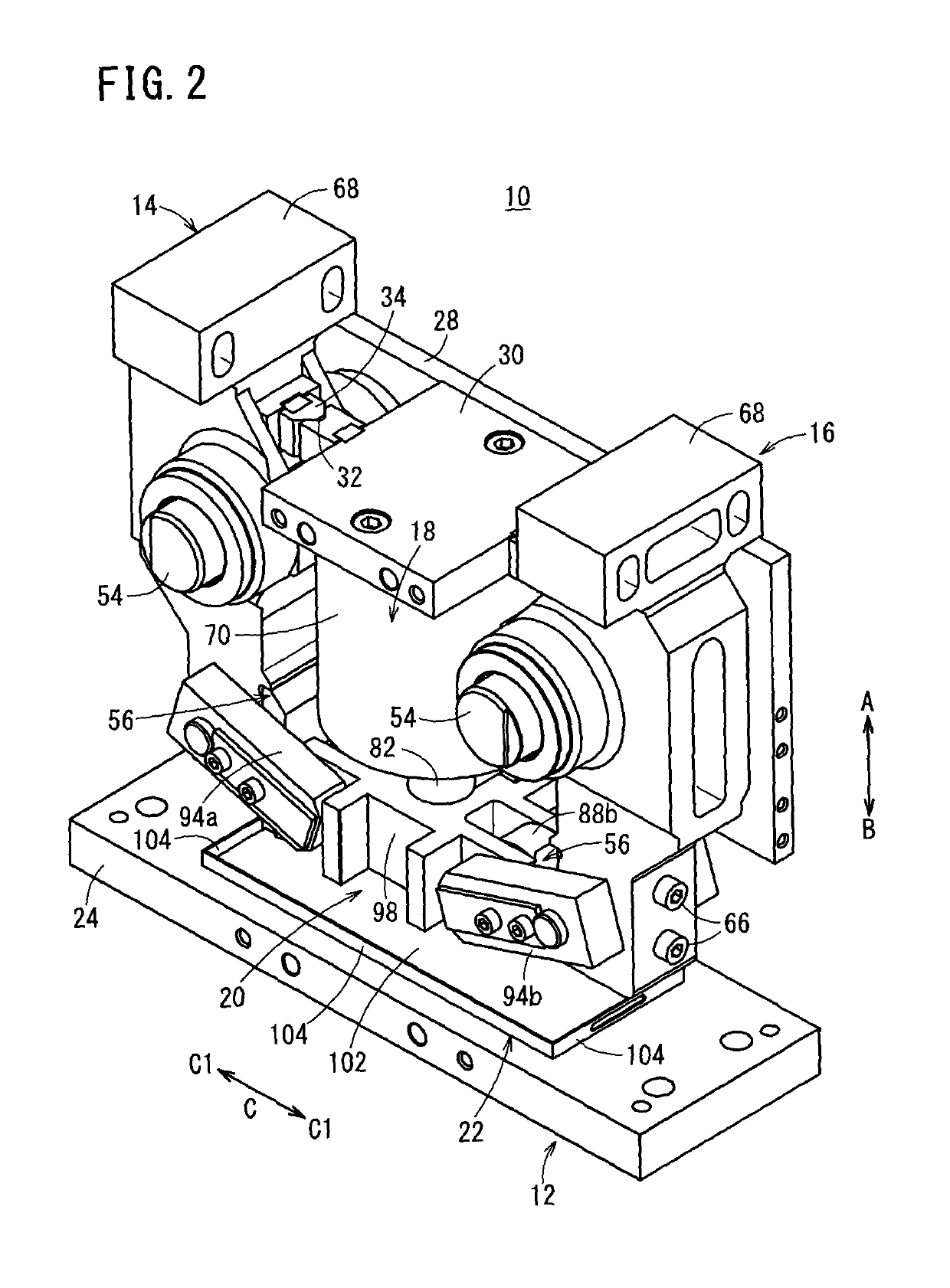
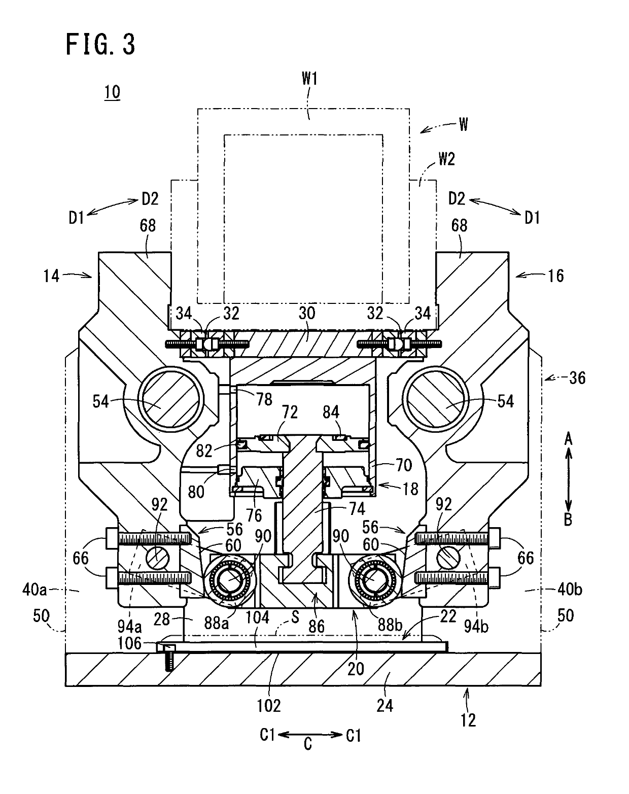
[0056]The clamp apparatus 10 according to the present invention is constructed basically as described above. Next, operations and advantages of the clamp apparatus 10 will be explained. In the following description, the unclamped condition, in which the gripping members 68 of the first and second clamp arms 14, 16 are separated mutually from each other, will be described as an initial position. In the initial position, pressure fluid is supplied to the second port 80, and a state is assumed in which the piston 72 is raised, whereby the first and second clamp arms 14, 16 are rotated, via the block body 86 and the link arms 94a, 94b of the driving force transmission mechanism 20, about the arm pins 54 in directions (the directions of the arrows D1) so that the gripping members 68 are separated away from each other.

[0057]At first, in a state in which a workpiece W is placed on the ceiling portion 30, under a switching action of a non-illustrated switching device, the pressure fluid, wh...

second embodiment

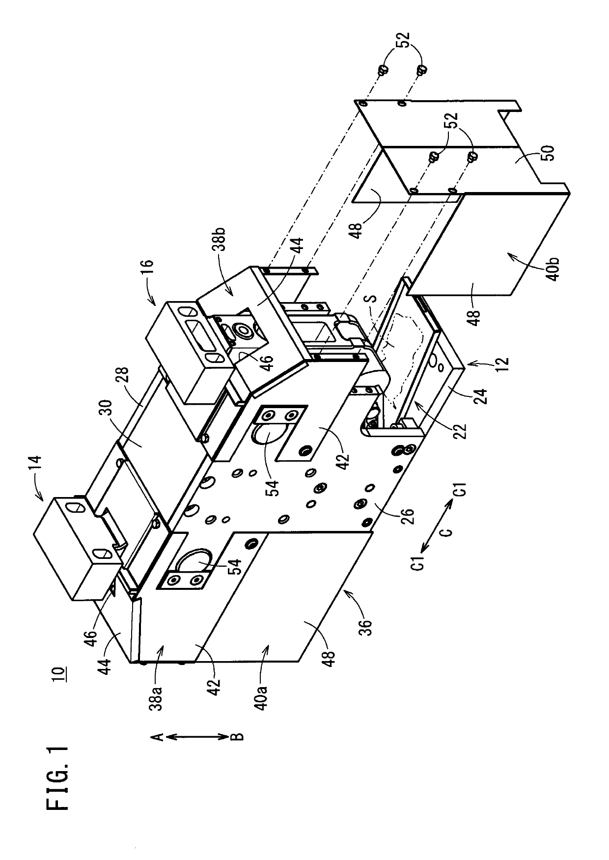
[0075]In the clamp apparatus 150 the unloading tray 22 is disposed inside the cover 36, at a position below the first and second clamp arms 14, 16 in the direction of gravity (the direction of the arrow B). Thus, during a welding operation on the clamped workpiece W, spatter S, which passes through the openings 46 of the cover 36 and invades into the interior, is suitably received by the unloading tray 22 and can be taken out to the exterior and eliminated easily and reliably through the unloading tray 22. In other words, the operation to remove and eliminate spatter can be preformed easily, and maintainability of the camp apparatus 150 can be enhanced.

[0076]Irrespective of the structures of the driving force transmission mechanisms 20, 152 in the clamp apparatus 10, 150 according to the first and second embodiments, by providing the unloading tray 22 in the interior of the clamp apparatus, the removal operation for eliminating spatter S that has invaded into the apparatus can be p...


PUM


Abstract

A clamp apparatus including first and second clamp arms, which are supported rotatably on a body, with a cover being installed to cover outer sides of the body. The cover includes openings through which portions of the first and second clamp arms are inserted and rotatably operated. An unloading tray is arranged in the body at a position below the openings in the direction of gravity. Spatter, which invades into the clamp apparatus from the openings when a welding operation is carried out on a workpiece that is clamped by the first and second clamp arms, is deposited on the unloading tray, and the spatter is eliminated by taking out the unloading tray to the exterior of the clamp apparatus.

Description

TECHNICAL FIELD[0001]The present invention relates to a clamp apparatus for clamping workpieces on an automated assembly line or the like.BACKGROUND ART[0002]Heretofore, in an automated assembly line for automobiles, an assembly process has been performed in which clamping is carried out by a clamp apparatus under a condition in which pre-formed frames are positioned in an overlaid manner and the frames are welded together.[0003]In one such clamp apparatus, as disclosed in Japanese Patent No. 4950123, left and right clamp arms are provided as a pair, the clamp arms being disposed for rotation respectively through pins. Further, proximal ends of the clamp arms are supported pivotally by a base to which a drive unit in the form of an air cylinder is connected, whereby distal ends of the clamp arms are operated to open and close. Thus, a workpiece such as a frame or the like is gripped from the left and right by the distal ends of the pair of clamp arms.SUMMARY OF THE INVENTION[0004]Wi...

Claims


Application Information

Patent Timeline
Patent Type & Authority Patents(United States)
IPC IPC(8): B25B1/08B25B5/06B25B5/16
CPCB25B5/16B25B5/064
Inventor FUKUI, CHIAKITAKAHASHI, KAZUYOSHISASAKI, HIDEKIKOBAYASHI, MASAHARU
Owner SMC CORP
Why Eureka
Try Eureka