Method and device for deflection of space debris

a technology of space debris and deflection device, which is applied in the field of space pollution, can solve the problems of affecting the function of active satellites, and affecting the stability of active satellites

Active Publication Date: 2019-07-02
CENT NAT DETUD SPATIALES (CNES)
View PDF6 Cites 1 Cited by
  • Summary
  • Abstract
  • Description
  • Claims
  • Application Information

AI Technical Summary

Problems solved by technology

Space debris rise two different types of problems: risk for populations on the ground during uncontrolled atmospheric re-entry (not addressed here), and the risk of collision in orbit between space objects.
The consequences of collisions are of two orders:a collision, even due to very small debris, can damage an active satellite and have it lose functions.
Regeneration of debris by collision between large debris makes the international community fear a “Kessler syndrome”, i.e., an uncontrollable rise in the number of items of orbital debris by mutual collisions, in the long run posing a growing risk of collision on operational satellites.
One particular collision scenario rises a different problem: collision between two large catalogued debris but without capacity to manoeuvre can prove predictable without being avoidable as such.
There can be the situation of calculating a high collision probability in 24 to 48 hours between two old integrated satellites without being able to prevent it, therefore without being able to prevent generation of a few thousand of new debris.
Such solutions are complex to perform and raise many safety problems.
But according to the authors of this document, several problems arise.
A relevant cloud can comprise fine solid particles, tungsten for example, or by contrast droplets of water, the former having the drawback of falling by passing through all orbits to the point of atmospheric re-entry, potentially risking damaging active satellites, the latter subliming rapidly in the void and therefore disappearing too fast, imposing often excessive cloud sizes.
To resolve this problem the authors of this document suggest using a balloon having very fine walls and containing the cloud, through which the debris has passed but which brings up many unknown issues especially relative to interaction between debris and the wall of the balloon, at orbital speed.
The preceding techniques therefore present drawbacks.

Method used


Image

  • Method and device for deflection of space debris
  • Method and device for deflection of space debris
  • Method and device for deflection of space debris

Examples


example of application

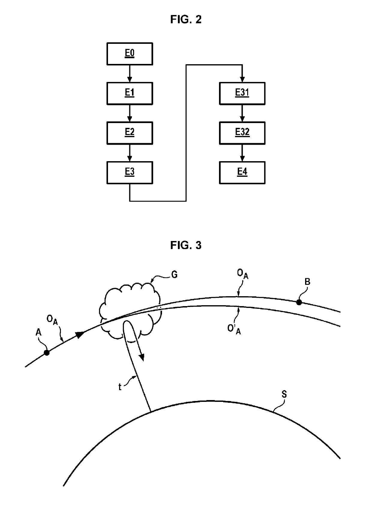
[0072]The most disturbing catalogued debris are on relatively high and sharply inclined orbits, typically between 700 and 1000 km in altitude, with an inclination greater than 80°. There are two debris in orbit at 850 km in altitude here, 98.6° in inclination. Relevant here is the most critical debris known to date, the 3rd stage of the Cosmos 3M launcher, of mass of 1.5 tons and a surface of around 12 m2.

[0073]There is also the probable average case of advance warning of 24 h, causing launching 12 hours prior to the collision as announced, i.e., 14 orbits.

[0074]If the aim was a change in altitude of perigee of 1 km for debris A, the decrement in speed ΔV to be supplied is 0.2569 m / s. But this also causes a change in period of the debris, decreasing by 0.6346 s. This decrease in period, integrated over 14.13 orbits, means that debris A will pass 14.13×0.6346=8.96 s before debris B at the predicted site of their collision. At the orbital speed of 7426.014 m / s (for this altitude), thi...


PUM


Abstract

The invention relates to a method for deflecting space debris comprising steps of:launching (E2) a thruster (2) by means of a sounding rocket (1) at a target altitude close to that of the one or more debris to be deflected.generating (E3) by the thruster a gas cloud (G) above the sounding rocket.

Description

CROSS REFERENCE TO RELATED APPLICATION[0001]This application claims the benefit of the filing date of French Patent Application No. 1561054, filed Nov. 17, 2015, the disclosure of which is incorporated herein by reference.GENERAL TECHNICAL FIELD[0002]The invention relates to the field of space pollution which is defined by the presence in the space of space debris in orbit around the Earth.PRIOR ART[0003]Space debris rise two different types of problems: risk for populations on the ground during uncontrolled atmospheric re-entry (not addressed here), and the risk of collision in orbit between space objects.[0004]Various cases exist concerning collisions in orbit, distinguished both as detectable and catalogued objects and also as untracked small objects:[0005]catalogued objects having a typical size of the order of 10 cm in low orbit are tracked by American Army radar networks and are the object of a catalogue for forecasting their trajectory, with precision dependent on the size of...

Claims


Application Information

Patent Timeline
Patent Type & Authority Patents(United States)
IPC IPC(8): B64G1/40B64G1/00B64G1/56B64G1/24B64G1/10
CPCB64G1/403B64G1/007B64G1/56B64G1/242B64G1/404B64G1/1078B64G1/002B64G1/005B64G1/66B64G1/2427
Inventor BONNAL, CHRISTOPHE
Owner CENT NAT DETUD SPATIALES (CNES)
Why Eureka
Try Eureka