Front-loader arrangement

a front-loader and arrangement technology, applied in the direction of cranes, lifting devices, constructions, etc., can solve the problems of requiring relatively complex production and assembly efforts, lock bolts, etc., and achieve the effect of simple and compact construction

Active Publication Date: 2019-07-02
DEERE & CO
View PDF9 Cites 0 Cited by
  • Summary
  • Abstract
  • Description
  • Claims
  • Application Information

AI Technical Summary

Benefits of technology

[0004]According to the invention, a front-loader arrangement of the type named above is formed such that the locking element is connected, advantageously rigidly, by means of a connection element to an actuation element arranged offset parallel to the locking element, wherein the actuation element can be actuated by an external force and the locking element can be displaced by means of the connection element and by actuation of the actuation element out from the unlocked position into the locked position. Through the arrangement of an actuation element in connection with a connection element that functions as a kind of bridge between the actuation element and the locking element, the locking element can be formed in an uncomplicated and simple way and can be supported on the mast arrangement. A connection element that can have a similarly uncomplicated and simple construction, for example, a connection plate, a connection rod, a connection bar, a connection tube, etc., allows the indirect actuation of the locking element by an external force, for example, by a spring force or by a connected hydraulic, pneumatic, electric, or mechanical actuator, wherein the locking element is carried along by means of the connection element when the actuation element is actuated or displaced or moved. The external force acting on the actuation element can be transmitted onto the locking element and can act on this locking element. The geometric dimensions of the actuation element can be constructed arbitrarily, so that also here a simpler and more compact construction is aided, because, with respect to other actuation means or actuation elements required for actuation, they are not bound directly to the relatively large dimensions of a locking element.
[0005]The actuation element and the locking element are supported or guided displaceably on the mast arrangement, wherein the locking element is displaced, guided parallel, when the actuation element is displaced together with the actuation element. The mast arrangement is formed by two mirror-inverted plates that lie opposite each other and are connected to each other by means of one or more crosspieces. The mentioned displaceable support of the actuation bolt could be performed, for example, by means of recesses formed opposite each other on the two plates, wherein the actuation element can extend through or is guided into these recesses. The typically robust formation of a locking element on a front loader also allows a correspondingly robust support or guidance of the locking element that can absorb relatively large bearing forces. Accordingly, the guidance or support of the actuation element can turn out to be relatively simple and uncomplicated, because the large part of the forces acting on the actuation element is absorbed by the rigid connection between locking, connection, and actuation elements from the guidance or support formed for the locking element.

Problems solved by technology

It is disadvantageous here that, in particular, the formation and arrangement of the actuation element formed on the mast arrangement, as well as its connection to the locking bolt, require relatively complex production and assembly efforts.

Method used


Image

  • Front-loader arrangement
  • Front-loader arrangement
  • Front-loader arrangement

Examples


Embodiment Construction

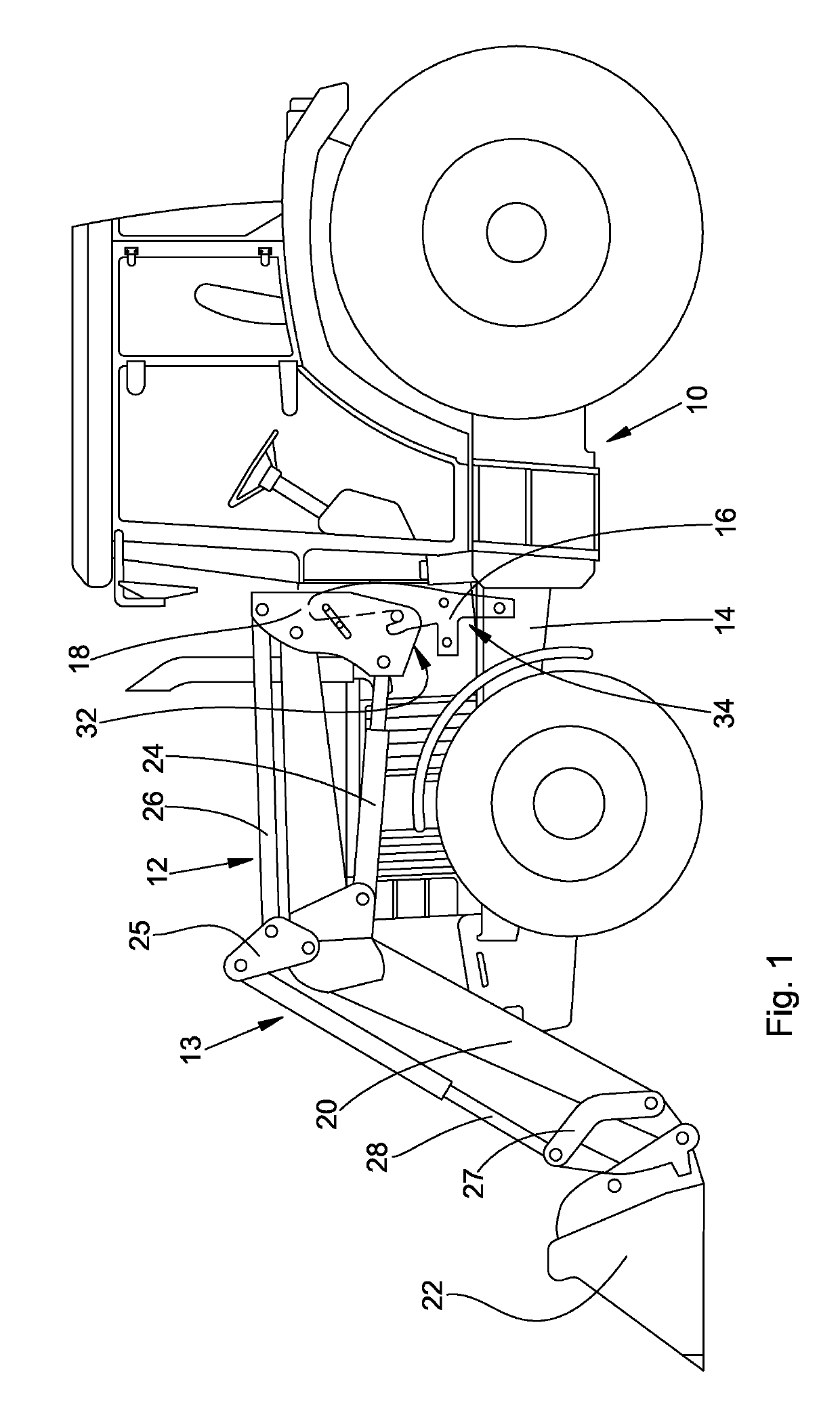
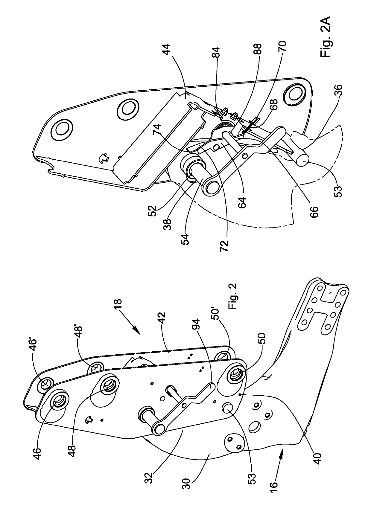
[0024]In FIG. 1, a loading vehicle in the form of an agricultural tractor is shown. The tractor 10 provides an attached front-loader arrangement 12. The front-loader arrangement 12 comprises a front loader 13, as well as a frame arrangement or bracket 16 attached to a vehicle frame 14 of the tractor 12. The front loader 13 has a mast arrangement 18 by means of which the front loader 13 is attached to the bracket 16 of the front-loader arrangement 12 on the tractor 10.

[0025]The front-loader arrangement 12 or the front loader 13 further has a front-loader link 20 that is fastened to the mast arrangement 18 so that it can pivot and to which a pivoting front-loader tool 22 attaches. The front-loader tool 22 is formed, for example, in the form of a loading bucket, wherein the front-loader tool 22 could also be constructed as a loading fork, gripper, etc. The front-loader link 20 can pivot by means of a hydraulic lifting cylinder 24 that extends between the mast arrangement 18 and the fro...


PUM


Abstract

A front-loader arrangement (12) for an agricultural vehicle (10) with a bracket (16) and a mast arrangement (18) for fastening a front loader (13) to the bracket (16). The mast arrangement (18) comprises a contact point (53) for application onto a bearing point (36) of the bracket (16) and a displaceable locking element (54) that extends through at least one first opening (52, 52A) formed on the mast arrangement (18) and through at least one second opening (38) brought into alignment with the first opening (52, 52A). The locking element (54) is connected by a connection element (56) to an actuation element (58) arranged offset parallel to the locking element (54). The actuation element (58) can be actuated by an external force and the locking element (54) can be displaced by the connection element (56) and by the actuation of the actuation element (58) from the unlocked position into the locked position.

Description

FIELD OF THE INVENTION[0001]The invention relates to a front-loader arrangement for an agricultural vehicle with a bracket and a mast arrangement for fastening a front loader to the bracket.BACKGROUND OF THE INVENTION[0002]Front-loader arrangements, i.e., the arrangement of a front loader on a vehicle, especially on an agricultural vehicle, or also on a different type of utility vehicle, are known. Thus, front loaders can be attached to or mounted on a vehicle, for example, a tractor or an agricultural tractor, by means of a mounting frame or bracket, in order to carry out loading work. The mounting frame or the bracket is typically screwed onto the vehicle frame or is fastened to this vehicle frame. The front loader itself provides an attachment or mounting point or mast arrangement that is attached or mounted or hinged to the bracket. In this respect, different possibilities are known. Thus, some known embodiments for front-loader arrangements have mechanisms that provide two hook...

Claims


Application Information

Patent Timeline
Patent Type & Authority Patents(United States)
IPC IPC(8): E02F3/627E02F3/36
CPCE02F3/627E02F3/6276E02F3/3645
Inventor ROHOU, DAVID
Owner DEERE & CO
Why Eureka
Try Eureka