Hydrostatic linear drive system

a linear drive and linear drive technology, applied in the direction of pumps, accumulator installations, presses, etc., to achieve the effects of higher retraction and extension speed, simple and compact construction, and higher for

Active Publication Date: 2020-10-29
KRUPP KAUTEX MASCHINENBAU GMBH
View PDF0 Cites 0 Cited by
  • Summary
  • Abstract
  • Description
  • Claims
  • Application Information

AI Technical Summary

Benefits of technology

[0008]An object of the invention is to provide a linear drive system which has a simpler and more compact construction than the prior art, with at the same time higher retraction and extension speed in rapid mode, higher forces in power mode, and reduced energy consumption.

Problems solved by technology

During the extension movement in power mode, however, the hydraulically active faces cooperate with each other which contributes to high forces with a compact structure of the drive system.

Method used


Image

  • Hydrostatic linear drive system
  • Hydrostatic linear drive system
  • Hydrostatic linear drive system

Examples


first embodiment

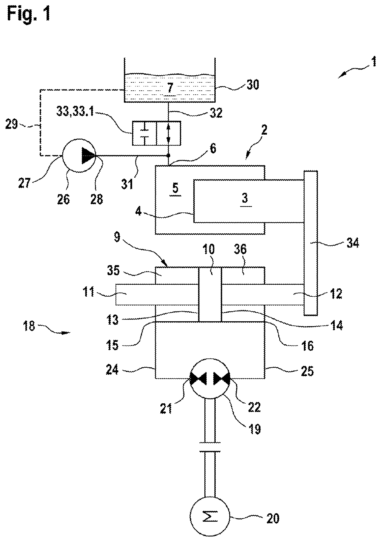
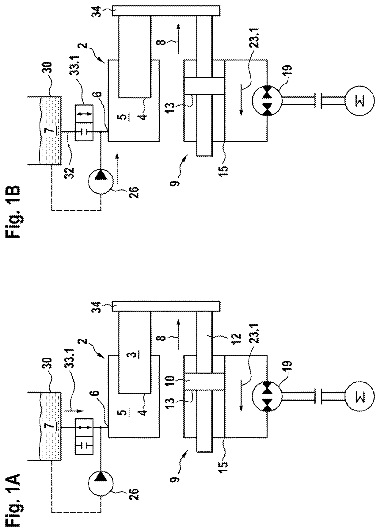
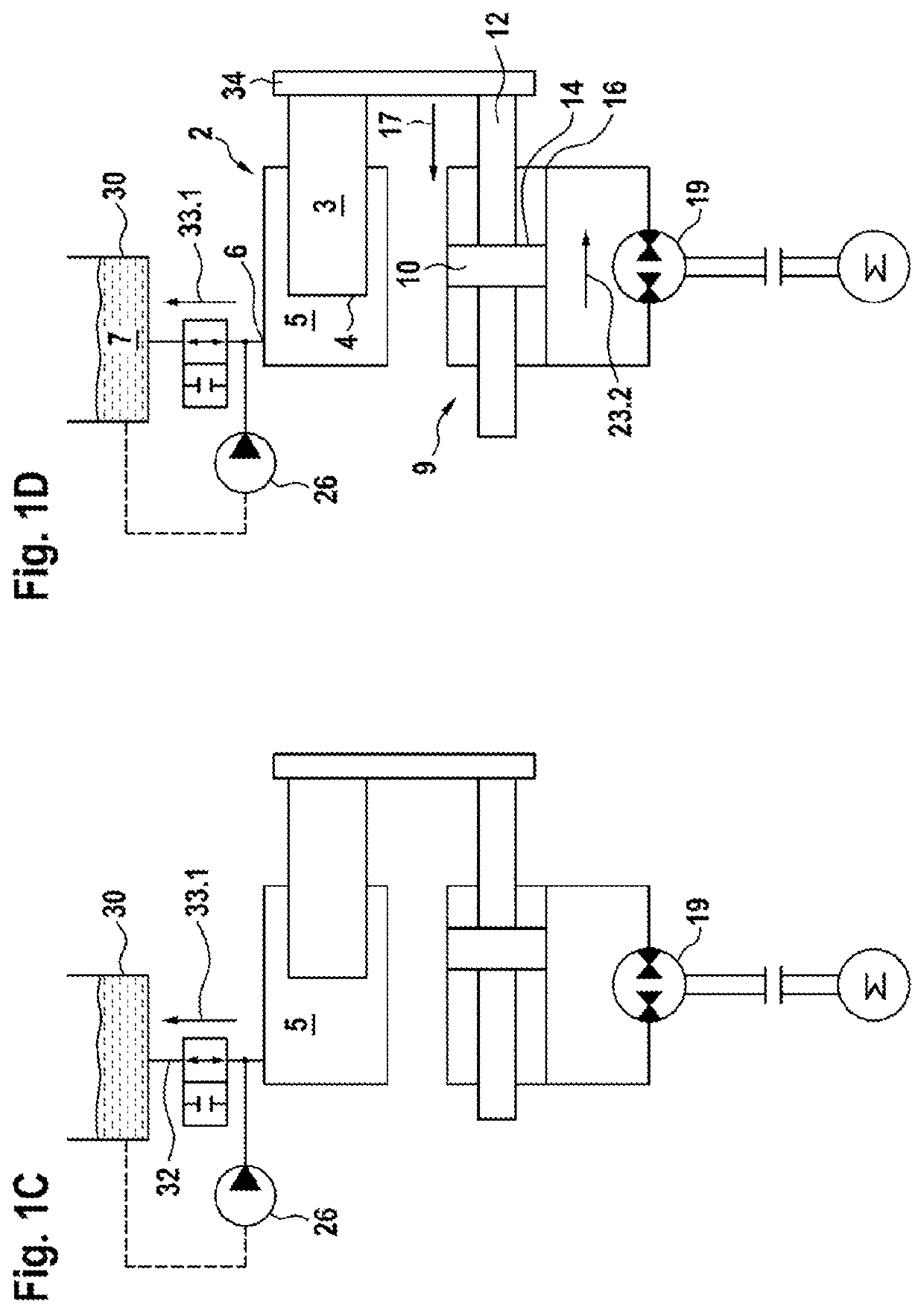
[0050]FIG. 1 shows a hydrostatic linear drive system 1 having a single-action cylinder 2 which is constructed as a plunger cylinder. The plunger cylinder comprises a piston rod 3, a first hydraulically active face 4 and a first cylinder chamber 5 having a first fluid connection 6 for a hydraulic fluid 7. As a result of the construction of the single-action cylinder 2 as a plunger cylinder, the piston rod 3 is at the same time the piston. The end side of the piston rod 3 facing the cylinder chamber 5 is the piston face and is hydraulically active.

[0051]The first hydraulically active face 4 of the single-action cylinder 2 can be acted on with the hydraulic fluid 7 via the first fluid connection 6 in an extension direction 8 (see FIG. 1A).

[0052]Referring back to FIG. 1, the linear drive system 1 further has a synchronous cylinder 9 which has at both sides of the piston 10 a piston rod 11, 12. The annular piston faces which surround the piston rods 11, 12 form a second hydraulically act...

second embodiment

[0064]FIG. 2 shows a hydrostatic linear drive system 1 having a single-action cylinder 2, which is constructed as a plunger cylinder. The plunger cylinder comprises a piston rod 3, a first hydraulically active face 4 and a first cylinder chamber 5 with a first fluid connection 6 for a hydraulic fluid 7. As a result of the construction of the single-action cylinder 2 as a plunger cylinder, the piston rod 3 is at the same time the piston. The end side of the piston rod 3 facing the cylinder chamber 5 is the first hydraulically active face 4.

[0065]The first hydraulically active face 4 of the single-action cylinder 2 can be acted on with the hydraulic fluid 7 in an extension direction 8 via the first fluid connection 6.

[0066]The linear drive system 1 further has a synchronous cylinder 9 which has at both sides of the piston 10 a piston rod 11, 12. The annular piston faces which surround the piston rods 11, 12 form a second hydraulically active face 13 and a third hydraulically active fa...

third embodiment

[0078]FIG. 3 shows a hydrostatic linear drive system 1 having a 3-face cylinder 42, which integrates the functions of the single-action cylinder 2 and the synchronous cylinder 9 of the embodiments according to FIGS. 1 and 2 in a sub-assembly. Components of the 3-face cylinder 42 which correspond in terms of function to the embodiments according to FIGS. 1 and 2 are given corresponding reference numerals. The 3-face cylinder 42 has a cylinder pipe 43, a cylinder base 44 which terminates the cylinder pipe 43 at an end side and a piston rod guide 45 which is arranged at the opposite end side. The piston rod guide 45 guides a piston rod 46 in an axial direction. An annular piston 47 is arranged at one end of the piston rod 46. From the cylinder base 44, a guiding pin 48 extends into the cylinder pipe 43. The annular piston 47 surrounds the guiding pin 48 and is moved in a sliding manner along the guiding pin 48 in an extension direction 8 (see FIGS. 3A and 3B) and a retraction direction...


PUM

PropertyMeasurementUnit
pretensioning pressureaaaaaaaaaa
atmospheric pressureaaaaaaaaaa

Abstract

A linear drive system, in particular for a closure unit of a blow mold installation, with a simpler and more compact structure, a higher retraction and expansion speed in rapid mode, higher forces in power mode, and reduced energy consumption, than the prior art includes a cylinder arrangement which brings about a retraction and extension movement in rapid mode by separate hydraulically active faces which are independent of a larger hydraulically active face which is acted on with pressurized hydraulic fluid only in power mode. During the extension movement in power mode, however, the hydraulically active faces cooperate which contributes to high forces with a compact structure of the drive system.

Description

CROSS-REFERENCE TO RELATED APPLICATIONS[0001]The present invention claims priority to DE 10 2019 110 917.5, filed Apr. 26, 2019, the entire contents of which are incorporated herein by reference.FIELD OF THE INVENTION[0002]The invention relates to a hydrostatic linear drive system, in particular for a closure unit of a blow mold installationBACKGROUND OF THE INVENTION[0003]Hydrostatic linear drive systems are used, for example, in hydraulic presses, deep-drawing or injection-molding machines. Such machines generally have a plurality of movement sequences. One of these movement sequences is a power mode in which a high force is applied at low speed to a workpiece which is intended to be processed or a component which is intended to be moved. Another of these movement sequences is a rapid mode in which a smaller force is applied but enables a more rapid movement.[0004]Such a linear drive system is known, for example, from DE 10 2016 113 882 A1. The known linear drive system has a hydr...

Claims


Application Information

Patent Timeline
Patent Type & Authority Applications(United States)
IPC IPC(8): F15B15/18F15B15/14F15B1/02
CPCF15B15/149F15B15/18F15B1/021F15B11/04F15B11/17F15B11/22F15B1/024F15B13/06B30B15/161B29C49/56F15B2211/20576F15B2211/212F15B2211/782F15B11/036F15B11/022F15B2211/20561F15B2211/27F15B2211/20546F15B2211/7055F15B2211/775F15B1/26
Inventor WELLENBERG, ARNDTTSCHEKORSKY ORLOFF, MINKA
Owner KRUPP KAUTEX MASCHINENBAU GMBH
Why Eureka
Try Eureka