
Methods and apparatus for vertical hanging plant container

a technology of vertical hanging and plant container, which is applied in the direction of self-acting watering devices, horticulture, agriculture, etc., can solve the problems of rotting of plant roots, damage to long-term plant health, and overexposure of plants

Active Publication Date: 2019-07-09
WALLYGRO LLC
View PDF41 Cites 4 Cited by
  • Summary
  • Abstract
  • Description
  • Claims
  • Application Information

AI Technical Summary

Benefits of technology

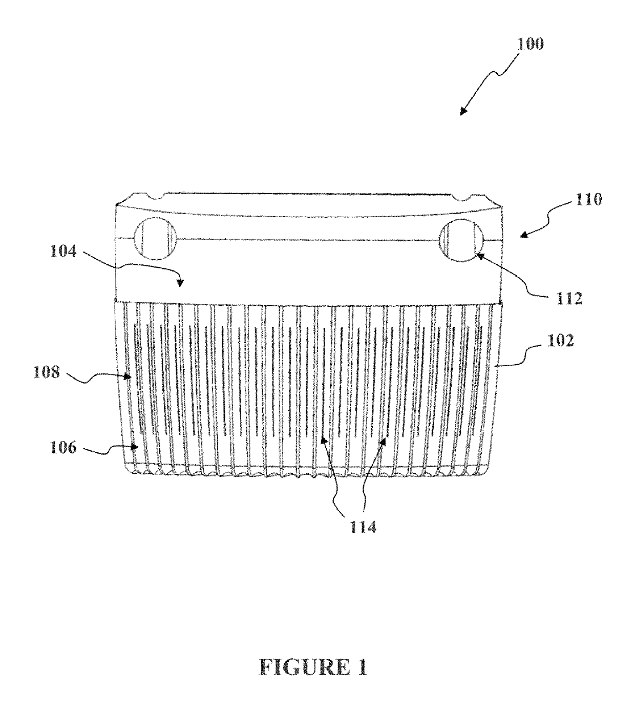
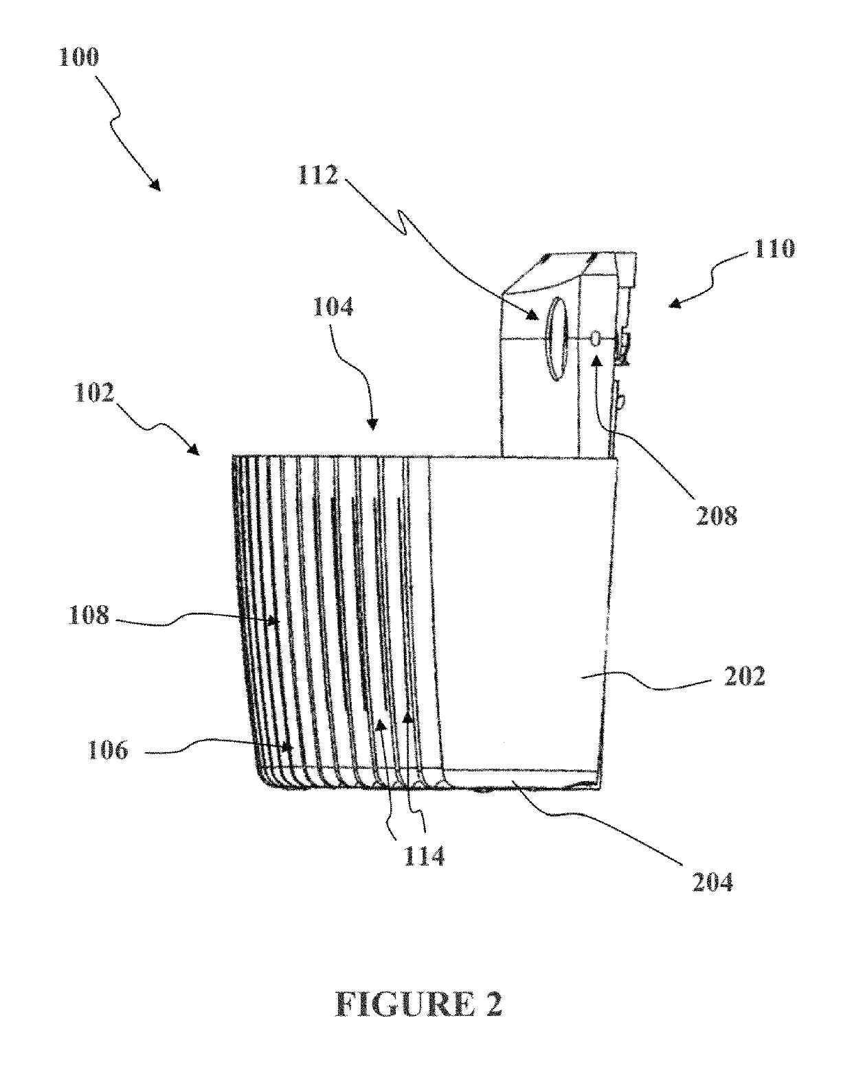
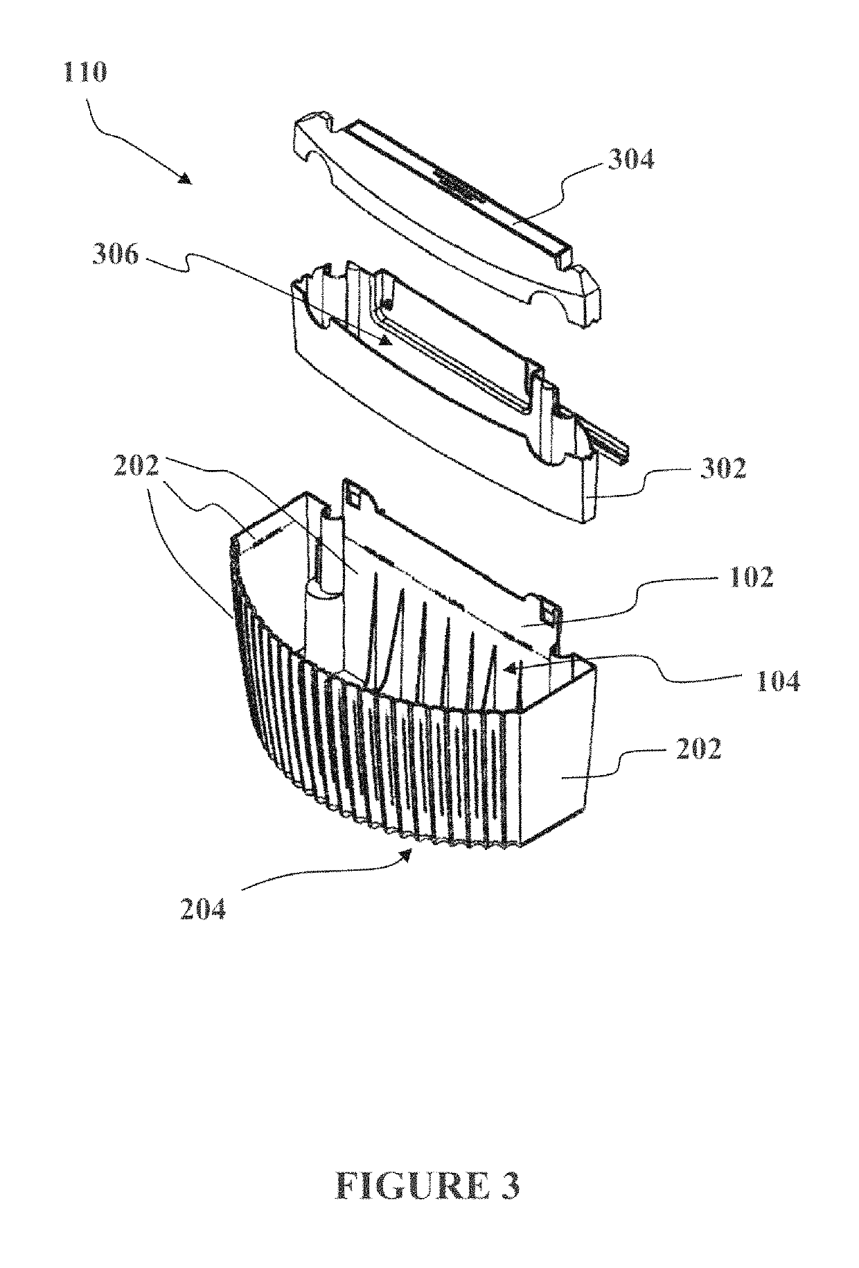
The present technology provides methods and apparatus for vertical hanging plant containers. These containers have a moisture impermeable reservoir and at least one breathable zone. The reservoir allows moisture to be stored and wicked upwards by the soil in the container. The breathable zones allow air and moisture to transfer between the soil and the external environment. The interior divider separating two interior portions of the container has a second breathable zone. These technical effects provide improved plant growth and health by ensuring optimal moisture and air conditions.

Problems solved by technology

Impermeability of some materials to air, moisture, and water may damage long-term plant health, especially where the amount of soil held by the container is small.
For example, micro-porous materials may not allow water to permeate the container fast enough and result in overexposing the plant to moisture, which can cause rotting of the plant roots.
However, over longer time periods, the lack of a water impermeable layer can eventually result in the micro-porous material allowing condensation to seep through the bottom and sidewalls of the container, since it is not absorbent enough to provide condensation protection.
Further, the escaping water may cause damage and / or create an undesired situation to surrounding areas.

Method used


Image

  • Methods and apparatus for vertical hanging plant container
  • Methods and apparatus for vertical hanging plant container
  • Methods and apparatus for vertical hanging plant container

Examples


Embodiment Construction

[0022]The present technology relates to as hanging planter comprising at least one breathable zone and a water retaining section. More specifically the present technology relates to a hanging planter that may be formed as a vessel for retaining plants in a substantially vertical position, such as being mounted, hung, or otherwise coupled to a wall or ceiling. The present technology may be described in terms of functional block components and various processing steps. Such functional blocks may be realized by any number of components configured to perform the specified functions and achieve the various results. For example, the present technology may employ various types of materials, fasteners, ducting, storage containers, and the like, which may carry out a variety of functions. In addition, the present technology may be practiced in conjunction with any number of processes such as garden planting, plant training, decorating, and the system described is merely one exemplary applica...


PUM


Abstract

Methods and apparatus for a vertical hanging plant container comprise a container comprising a moisture impermeable reservoir and at least one breathable zone positioned above the reservoir. The reservoir may be disposed along a bottom section of the container to serve as a moisture storage region allowing moisture to be wicked upwards by the soil in the container. A first breathable zone may be located above the reservoir in at least one sidewall of the container and allow for the transfer of air and moisture between the soil and an exterior environment surrounding the container. A second breathable zone may be located above the reservoir in an interior divider separating two interior portions of the container.

Description

CROSS-REFERENCES TO RELATED APPLICATIONS[0001]This application claims the benefit of U.S. Provisional Patent Application No. 61 / 922,476, Dec. 31, 2013 and is a Continuation-in-part of application of U.S. application Ser. No. 13 / 740,487 filed Jan. 14, 2013, which is a Continuation-in-part of application of U.S. application Ser. No. 13 / 066,950 filed Apr. 28, 2011 (now U.S. Pat. No. 8,567,122), which is a Continuation-in-part of International Application No. PCT / US2010 / 00743 filed on Mar. 10, 2010, and claims the benefit of U.S. Provisional Patent Application No. 61 / 209,768 filed Mar. 10, 2009, and U.S. Provisional Patent Application No. 61 / 336,985 filed Jan. 29, 2010 and incorporates the disclosure of each application in its entirety by reference. To the extent that the present disclosure conflicts with any referenced application, however, the present disclosure is to be given priority.BACKGROUND[0002]Plants are commonly grown out of the ground in various types of containers including...

Claims


Application Information

Patent Timeline
Patent Type & Authority Patents(United States)
IPC IPC(8): A01G27/02A01G9/02
CPCA01G27/02A01G9/022A01G9/02
Inventor NELSON, MIGUEL E.KUNST, ADLAI
Owner WALLYGRO LLC
Learn More