
Multibeam lighting system

a multi-beam, lighting system technology, applied in underwater equipment, lighting support devices, with built-in power, etc., can solve the problems of limited beam angle, robustness, and ease of use/portability, and achieve the effect of improving beam angle, portability and portability

Inactive Publication Date: 2019-07-09
GANAHL JOSEPH
View PDF11 Cites 21 Cited by
  • Summary
  • Abstract
  • Description
  • Claims
  • Application Information

AI Technical Summary

Benefits of technology

The patent describes a wearable lighting system that can be used for various applications such as underwater diving, camping, and hiking. The system includes a handheld lighting apparatus with multiple LED modules and a flexible support. The LED modules have brightness controls, strobe modes, and can be auto-dimming for heat control. The system can be powered by a battery and includes a power management system. It can be used for underwater diving at depths up to 300 feet and includes a waterproof housing. The system can also be used for hiking and includes a compass and a stand-on table for area lighting. Overall, the system provides a comfortable and versatile solution for lighting in various situations.

Problems solved by technology

Current solutions are limited in beam angle, robustness and ease of use / portability.

Method used


Image

  • Multibeam lighting system
  • Multibeam lighting system
  • Multibeam lighting system

Examples


embodiment 102

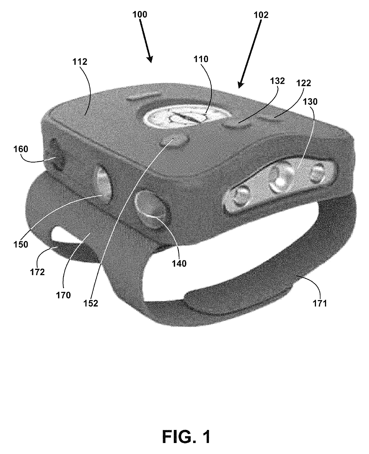
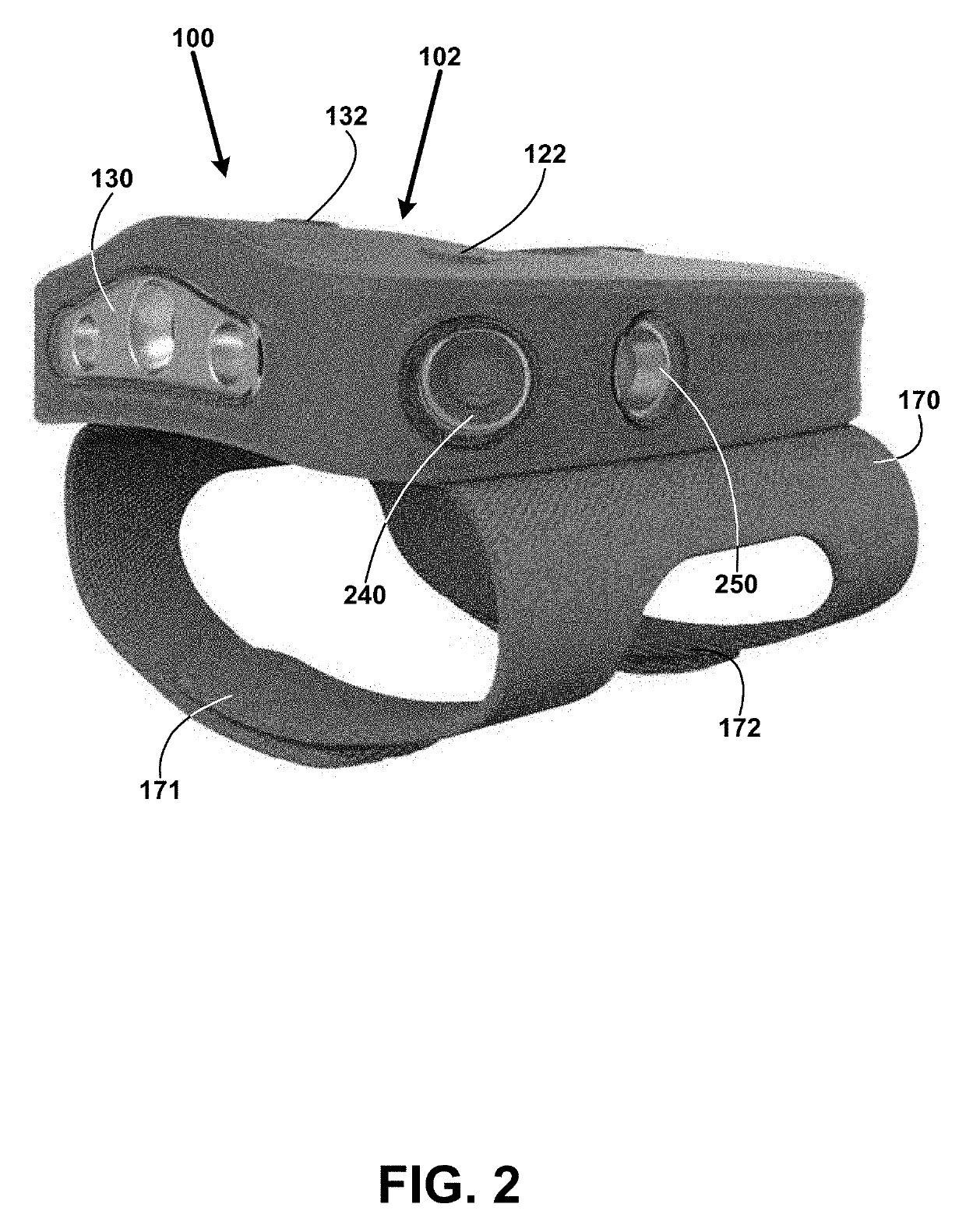
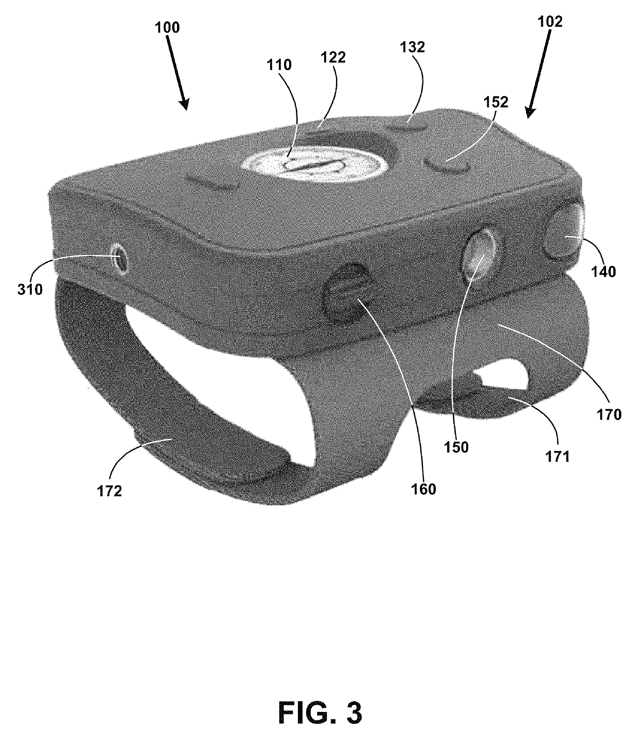
[0031]FIG. 1 shows for illustrative purposes an example of a wearable halo lighting system of one embodiment. FIG. 1 shows a wearable halo lighting system 100 in a right front view perspective. The wearable halo lighting system 100 includes a first wearable halo lighting system embodiment 102. The wearable halo lighting system 100 embodiments can include at least one component module including an integrated compass 110, a waterproof case 112, a left side LED / lens light pod control button 122, a left side LED / lens light pod 250 not shown, a front LED / lens light pod 130, a front LED / lens light pod control button 132, a right side LED / lens light pod 150, a right side LED / lens light pod control button 152, a charger / external battery waterproof connection 160, and a removable hand band 170 including a front hand band strap 171 and a rear hand band strap 172, wherein a user's thumb is positioned between the front and rear hand band straps.

[0032]LED / lens light pod modules can include at le...

embodiment 500

[0053]FIG. 10 shows for illustrative purposes an example of a halo lighting system interior layout of one embodiment. FIG. 10 shows the wearable halo lighting system 100 in the second wearable halo lighting system embodiment 500 with a partially transparent case illustration of a halo lighting system 1000 interior layout including light and lens modules 150 and 250, the left side LED / lens light pod control button 122, the front LED / lens light pod control button 132, a right side LED / lens light pod control button 152, the front LED / lens light pod 130, two batteries 1008, the removable hand band 170, front hand band strap 171, an accessories mounting socket seat 1010, and the charger / external battery waterproof connection 160. The two batteries 1008 can be configured to include for example 18650 batteries (2600 mAh) of one embodiment.

Halo Lighting System WIFI, Bluetooth, Cellular and Satellite Connectivity:

[0054]FIG. 11A shows for illustrative purposes an example of halo lighting syst...


PUM


Abstract

The embodiments disclose a lighting device configured for projecting at least a 180 degree halo of light using at least one component module having a LED / lens light pod module, a mount configured for a user to wear the lighting device on a user's hand, at least one external battery pack and a navigation light device with the lighting device, wherein the lighting device and the navigation light device are configured to project a 360 degree light pattern and at least one sensor configured to automatically activate a front LED / lens light pod module when the user raises and points a hand to gain a predetermined distance forward focused beam in a pointing direction, wherein the at least one sensor activates left and right side LED / lens light pod modules for projecting a light pattern to a front and rear direction when the user's arm is at one's side.

Description

FIELD OF THE INVENTION[0001]The present invention relates to hand portable light systems. More specifically, this invention describes an ergonomic, rugged, compact, portable apparatus and method for a structure which encloses multiple LED / Lens pods along with a battery. The invention creates multi directional and / or at least a 180 degree light patterns, resembling a halo like circular light, with a lightweight, wearable and mountable system.BACKGROUND OF THE INVENTION[0002]Hand Portable light systems are utilized by a wide range of people, for many different functions, in many different locations and circumstances. Current solutions are limited in beam angle, robustness and ease of use / portability. As usage of hand portable light systems continues to increase, so too does the need to easily deploy them, provide enhanced operational power and offer a greater range of usage flexibility. Additionally, due to electronic design of LED lights, more durable solutions are needed to withstan...

Claims


Application Information

Patent Timeline
Patent Type & Authority Patents(United States)
IPC IPC(8): F21V23/04F21L4/08F21V31/00F21V15/04F21V23/00F21V21/08F21V23/02F21Y115/10
CPCF21V31/005F21V15/04F21V23/003F21V23/0435F21V21/08F21L4/08F21V23/0471F21V23/023F21Y2115/10B63C11/26B63C2011/021F21L4/02F21S9/037F21V21/0885F21V21/32F21V33/0052B63B45/00
Inventor GANAHL, JOSEPH
Owner GANAHL JOSEPH
Learn More