Radiation imaging apparatus and method of controlling the same

a technology of imaging apparatus and control method, which is applied in the direction of radioation controlled devices, television systems, instruments, etc., can solve the problems of reducing and achieve the effect of increasing the accuracy of a

a technology of imaging apparatus and control method, which is applied in the direction of radioation controlled devices, television systems, instruments, etc., can solve the problems of reducing and achieve the effect of increasing the accuracy of a

US10349914B2Active Publication Date: 2019-07-16CANON KK

Image

  • Radiation imaging apparatus and method of controlling the same
  • Radiation imaging apparatus and method of controlling the same
  • Radiation imaging apparatus and method of controlling the same

Examples


Embodiment Construction

[0020]A preferred embodiment of the present invention will be described below with reference to the accompanying drawings. Note that the respective drawings are merely drawn for the purpose of explaining structures and arrangements, and the scales of respective members shown in the drawings do not always reflect actual scales. Throughout the drawings, the same reference numerals denote the same members or components, and a repetitive description thereof will be omitted.

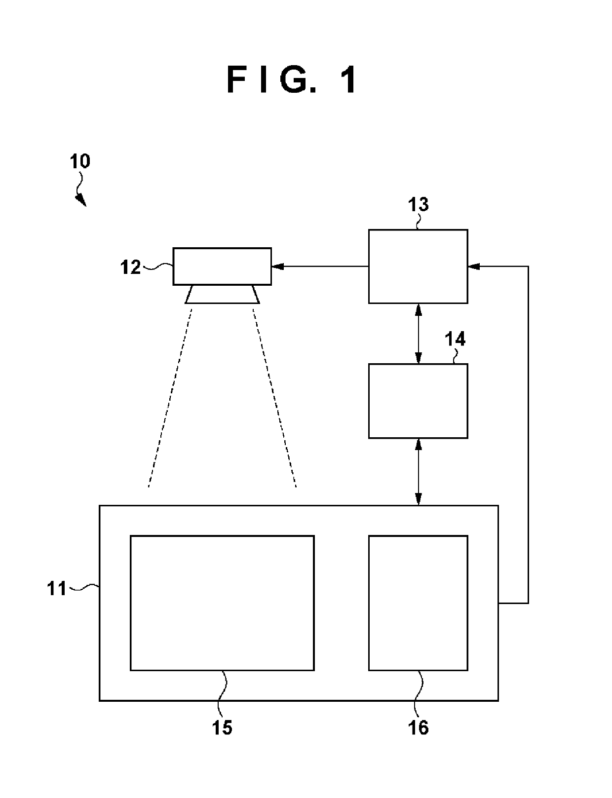
[0021]FIG. 1 shows an example of the system configuration of an imaging system 10 (to be also referred to as a radiation inspection apparatus, a radiation diagnostic apparatus, or the like) for performing radiation imaging. The imaging system 10 includes, for example, a radiation imaging apparatus 11, a radiation source 12, a radiation control unit 13, and a controller 14. The radiation imaging apparatus 11 includes an imaging unit 15 and a processor 16. The radiation source 12 generates radiation (for example, X-rays...


PUM


Abstract

A radiation imaging apparatus, including a plurality of pixels, a plurality of column lines and a processor, the plurality of pixels including first pixels and second pixels configured to generate signals of different values by receiving radiation rays of equal irradiation rates, and the plurality of pixels being arrayed such that their numbers are different between a first column and a second column of the plurality of columns, wherein the processor, after radiation irradiation is started, obtains a first signal of the first column and a second signal of the second column while maintaining each pixel to an OFF state and performs AEC based on the first and second signals.

Description

TECHNICAL FIELD[0001]The present invention relates to a radiation imaging apparatus and a method of controlling the same.BACKGROUND ART[0002]A radiation imaging apparatus includes, for example, a pixel array in which a plurality of pixels are arrayed to form a plurality of rows and a plurality of columns, and a readout unit for reading out a pixel signal from each pixel. In the pixel array, for example, a plurality of column lines respectively corresponding to the plurality of columns are arranged, and pixels on each column are connected to a corresponding column line. For example, each pixel includes a detecting element for detecting radiation, and a switch for connecting the detecting element and the corresponding column line. If the switch is turned on, a signal corresponding to an irradiation amount is transferred from the detecting element to the column line.[0003]Some radiation imaging apparatuses monitor signals from pixels after radiation irradiation for the pixel array star...

Claims


Application Information

Patent Timeline
16 Jul 2019
Publication
US10349914B2
IPC
G01T1/00; G01T1/208; H01L27/146; H04N5/355; G01T1/20; H04N5/361; A61B6/00; H04N5/32
CPC
A61B6/542; A61B6/4233; G01T1/208; G01T1/2018; H01L27/14612; H01L27/14663; H04N5/32; H04N5/35563
Inventors
TAKENAKA, KATSURO; YAGI, TOMOYUKI