Drive motor arrangement for a hydrostatic transmission

Active Publication Date: 2019-07-16
ROBERT BOSCH GMBH
View PDF11 Cites 2 Cited by
  • Summary
  • Abstract
  • Description
  • Claims
  • Application Information

AI Technical Summary

Benefits of technology

[0020]According to a second device-related, more complicated variant, the displacement change-over valve is a 5/2-way valve, via the deactivation position of which the inlet and the outlet of the further group are capable of connection to a c

Problems solved by technology

A disadvantage associated with suchlike drive motor arrangements is that their hydraulic motors always have a fixed displacement, s

Method used


Image

  • Drive motor arrangement for a hydrostatic transmission
  • Drive motor arrangement for a hydrostatic transmission

Examples


Embodiment Construction

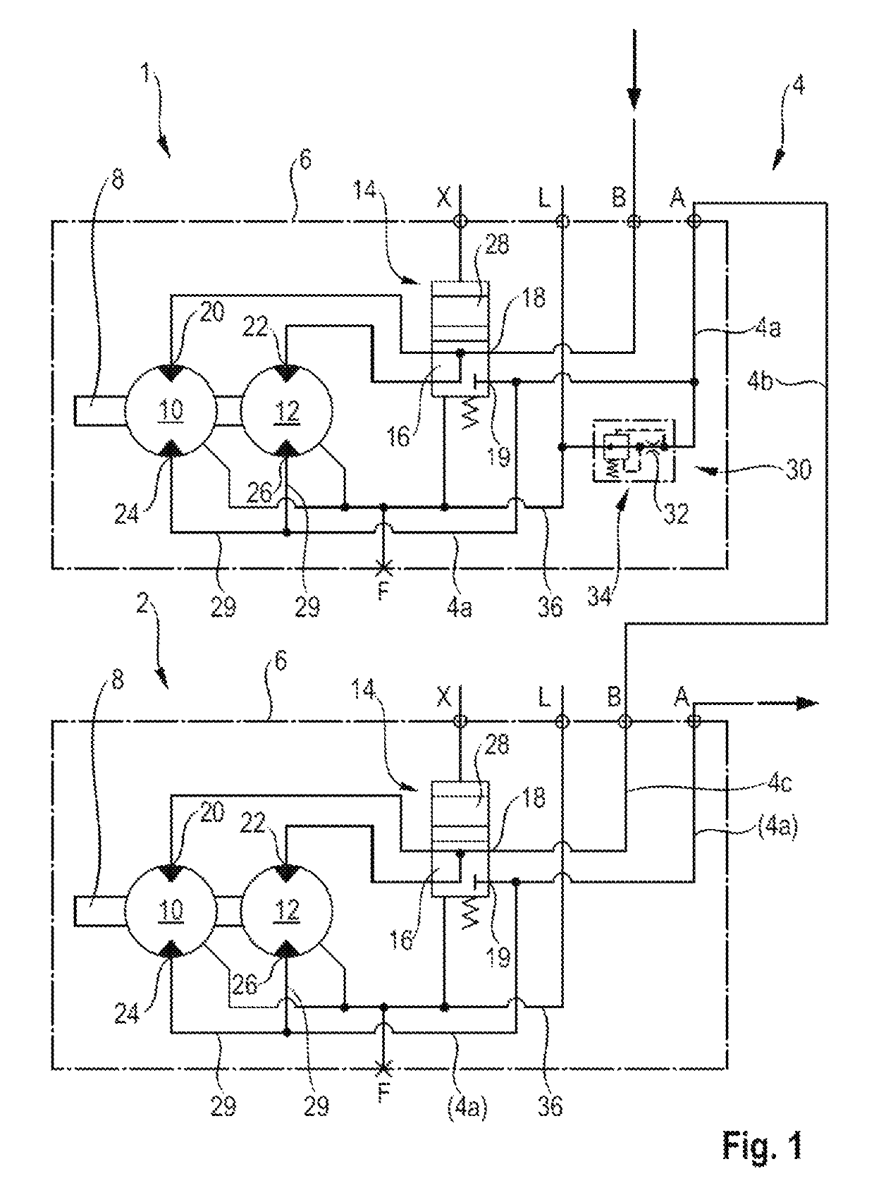
[0027]FIG. 1 depicts the first illustrative embodiment of the disclosed drive motor arrangement having a first radial piston motor 1 and a second radial piston motor 2, which are connected to one another in series. Pressure medium under high pressure is supplied to the inlet B of the first radial piston motor 1 via a pump, which is not illustrated here, and a closed hydraulic circuit. A connecting line 4 or, in particular, a main section 4b of the connecting line 4 is provided between an outlet A of the first radial piston motor and an inlet B of the second radial piston motor. In the second case, the connecting line 4 has a section 4a of connecting duct in the interior of the housing 6 of the first radial piston motor 1 and a section 4c of connecting duct in the interior of the housing 6 of the second radial piston motor 2.

[0028]The radial piston motors 1, 2 each have an output shaft 8, which is capable of being brought into operative interaction with a respective first group 10 an...


PUM


Abstract

A hydrostatic transmission includes a side having an upstream radial piston motor and a downstream radial piston motor. The motors are connected to each other in series via a connecting line. A flow control valve is configured to discharge pressure medium from the connecting line so that the downstream motor is only engaged in the event of a predetermined amount of slippage of the upstream motor. Each motor has at least two groups of working flanks. Each flank is configured to operatively interact with a high pressure, such that each motor has at least two transmission steps.

Description

[0001]This application claims priority under 35 U.S.C. § 119 to patent application no. DE 10 2016 216 382.5, filed on Aug. 31, 2017 in Germany, the disclosure of which is incorporated herein by reference in its entirety.[0002]The disclosure relates to a drive motor arrangement for a hydrostatic transmission having a first continuously driven hydraulic motor and a second hydraulic motor having the ability to be activated or engaged.BACKGROUND[0003]Publication DE 10 2010 015 498 A1 discloses a hydrostatic transmission, in which a left-hand and a right-hand drive motor arrangement are supplied via a common adjustable pump in a common closed circuit. The two hydraulic motors on each side and each drive motor arrangement are connected to one another in series. The two upstream hydraulic motors are driven in the course of the normal operation of the vehicle concerned in two-wheel drive mode, whereas the two downstream hydraulic motors are essentially only idling. A quantity of pressure me...

Claims


Application Information

Patent Timeline
IPC IPC(8): F16D31/02F16H61/4043B60K17/10F16H61/444
CPCB60K17/10F16H61/444F16H61/4043B60K17/356F16H61/4008F16H61/4061F16H61/423F16H61/44
Inventor EDWARD, IAIN
Owner ROBERT BOSCH GMBH
Why Eureka
Try Eureka