Sound receiving device and noise signal generating method thereof

Active Publication Date: 2019-07-16
CHICONY ELECTRONICS
View PDF1 Cites 0 Cited by
  • Summary
  • Abstract
  • Description
  • Claims
  • Application Information

AI Technical Summary

Benefits of technology

The present invention relates to a sound receiving device that generates noises using received current signals. The device comprises a power supply end, a linear voltage regulator module, a microphone, a digital modulation module, and a current limiting resistor. The device receives a power signal and converts it into a first current signal. The microphone then receives an external audio signal, and the digital modulation module processes it to become a digital audio signal. The current limiting resistor generates a second current signal, which is smaller than the first current signal and is insufficient to drive the digital modulation module. However, when the linear voltage regulator module receives a control signal, the second current signal is generated and outputted as a noise signal. The invention also provides a method for generating a noise signal. This technology allows for the generation of controlled noise in a sound receiving device, providing a novel feature and usefulness in various applications.

Problems solved by technology

Software-wise, it is prone to be attacked by hackers.
Further, if the volume of an input source of the microphone is directly turned down to minimum level or mute, it would easily cause its user to be confused with current usage state.

Method used


Image

  • Sound receiving device and noise signal generating method thereof
  • Sound receiving device and noise signal generating method thereof
  • Sound receiving device and noise signal generating method thereof

Examples


Embodiment Construction

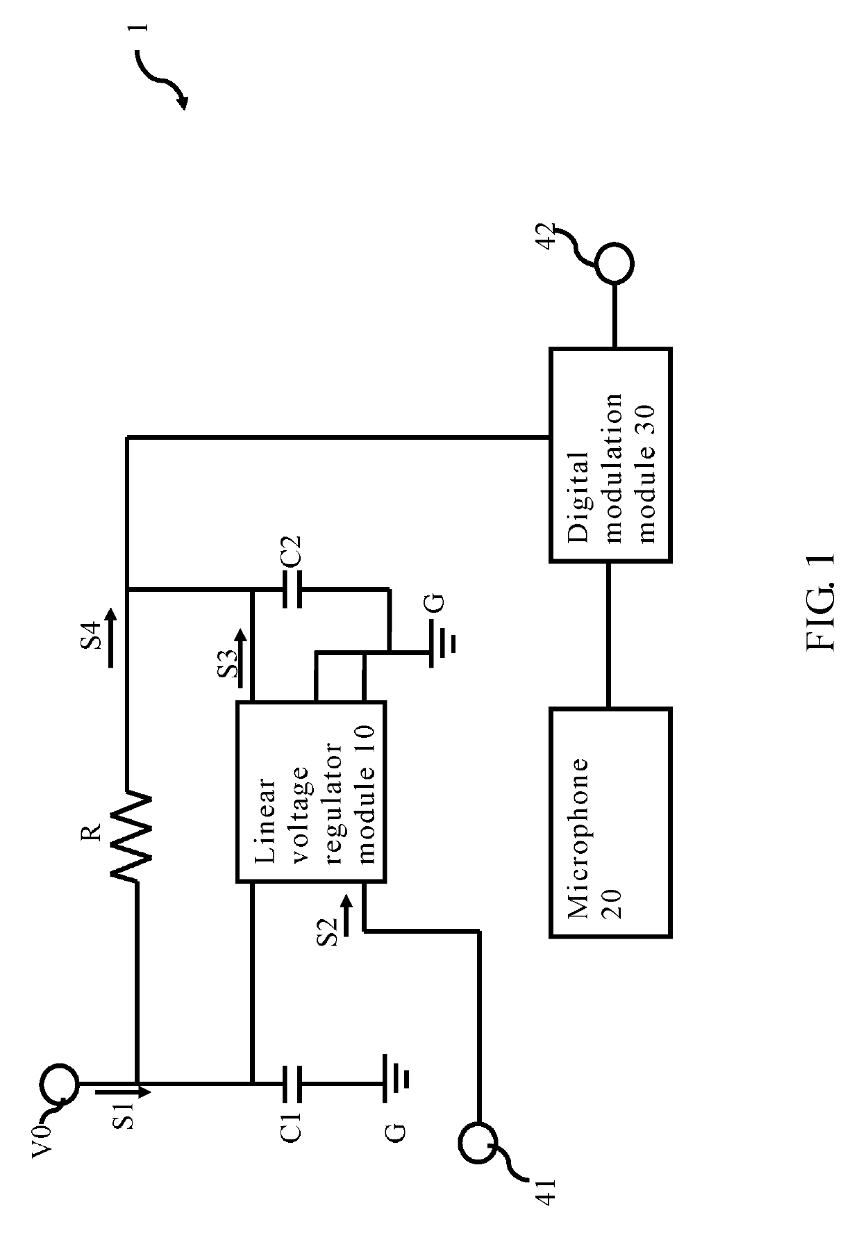
[0016]Please refer to FIG. 1, which illustrates a structural schematic drawing of a sound receiving device according to the present invention.

[0017]In one embodiment of the present invention, the sound receiving device 1 can be, without limiting the scope of the present invention, a smart phone, a tablet computer, a laptop computer or a desktop host, or partial assemblies of the abovementioned devices. The sound receiving device 1 comprises a power supply end V0, a linear voltage regulator module 10, a microphone 20, a digital modulation module 30 and a current limiting resistor R. Further, the sound receiving device 1 can also comprise capacitors C1, C2 and a grounding terminal G Because functions of the capacitors C1, C2 and the grounding terminal G are not key point to the present invention, there is no need for further description. Moreover, please note that the structural schematic drawing as shown in FIG. 1 is just for illustration purpose, while the scope of the sound receivi...


PUM


Abstract

A sound receiving device and a noise signal generating method thereof are disclosed. A linear voltage regulator module of the sound receiving device receives a power signal for converting into a first current signal. A microphone is used to receive an external audio signal. A digital modulation module receives the first current signal so as to process the external audio signal to become a digital audio signal. After the linear voltage regulator module receives a control signal, the first current signal is stopped, and the power signal is transmitted through a current limiting resistor to generate a second current signal to the digital modulation module, so that the digital modulation module generates and output a noise signal, wherein an amperage of the second current signal is less than an amperage of the first current signal and is not enough to normally drive the digital modulation module.

Description

BACKGROUND OF THE INVENTION[0001]1. Field of the Invention[0002]The present invention relates to a sound receiving device and a noise signal generating method thereof; more particularly, the present invention relates to a sound receiving device and a noise signal generating method thereof capable of generating noises by means of differences of received current signals.[0003]2. Description of the Related Art[0004]With the advance of technology, electronic devices, such as smart phones, tablet computers, laptop computers or even desktop hosts, equipped with cameras or microphones are common in modern life. However, privacy requests come along with such advance. Take microphone privacy problems as an example, in known prior arts, such problems can be solved by means of hardware or software. Hardware-wise, it is required to add a switch unit for a multiplexer or add an extra sound module in order to replace an output signal of a microphone by another sound source. Software-wise, it is p...

Claims


Application Information

Patent Timeline
IPC IPC(8): G10K11/175H04R29/00H04R3/00
CPCG10K11/175H04R29/00H04R3/00G10K11/18
Inventor LIN, WEN-CHANG
Owner CHICONY ELECTRONICS
Why Eureka
Try Eureka