Flow control device

a flow control and flow control technology, applied in the direction of valve details, liquid bottling, funnels, etc., can solve the problems of not always being able to selectively shut, not always being able to operate, and liquid loss, so as to improve the uniformity of force distribution and trouble-free operation of the device, improve the effect of operating reliability, and improve the assignment of individual components

Active Publication Date: 2019-07-23
BURKLE GMBH
View PDF25 Cites 2 Cited by
  • Summary
  • Abstract
  • Description
  • Claims
  • Application Information

AI Technical Summary

Benefits of technology

[0029]In a further advantageous embodiment of the invention, the flow control device is characterized in that the preloading device is designed as four first (south-north) bar magnets, supported on the flow channel, which are grouped around the center axis and reverse-axially-polarized in relation to the first ring magnet. This substantially improves the solution with two first (south-north) bar magnets explained above, since it is possible to achieve a more balanced assignment of the individual components due to the four bar magnets.
[0030]In yet a further advantageous embodiment of the invention, the flow control device is characterized in that, instead of one, it has two sliding tracks and link channels respectively integrated in its wall, which are situated opposite each other with regard to the center axis. With this solution according to the invention, it is also possible to significantly improve and balance the evenness of the force distribution and trouble-free operation of the device.
[0031]Finally, in yet another advantageous embodiment of the invention, the flow control device is characterized in that the first half of the bayonet mount and the second half, which can be releasably connected thereto, have devices for mutually centering and sealing the flow channel. This more advantageously increases operating reliability and simplifies handling. At the same time, an O-ring seal or a lip seal made of appropriate material can also be used.

Problems solved by technology

It is not always possible when handling liquids, for example in testing laboratories and during sampling for the purpose of quality control and similar applications, to prevent loss of material due to overflow or overdosing.
During filling and decanting operations, liquids are spilled which require cleaning effort that causes more or less problems depending on the quality of the liquids.
Commercially available, so-called all-purpose funnels generally have an unobstructed outflow, i.e. it is not possible to selectively shut off a liquid in the funnel container.
There is a risk in this case of losing liquid due to spillage.

Method used


Image

  • Flow control device
  • Flow control device
  • Flow control device

Examples


Embodiment Construction

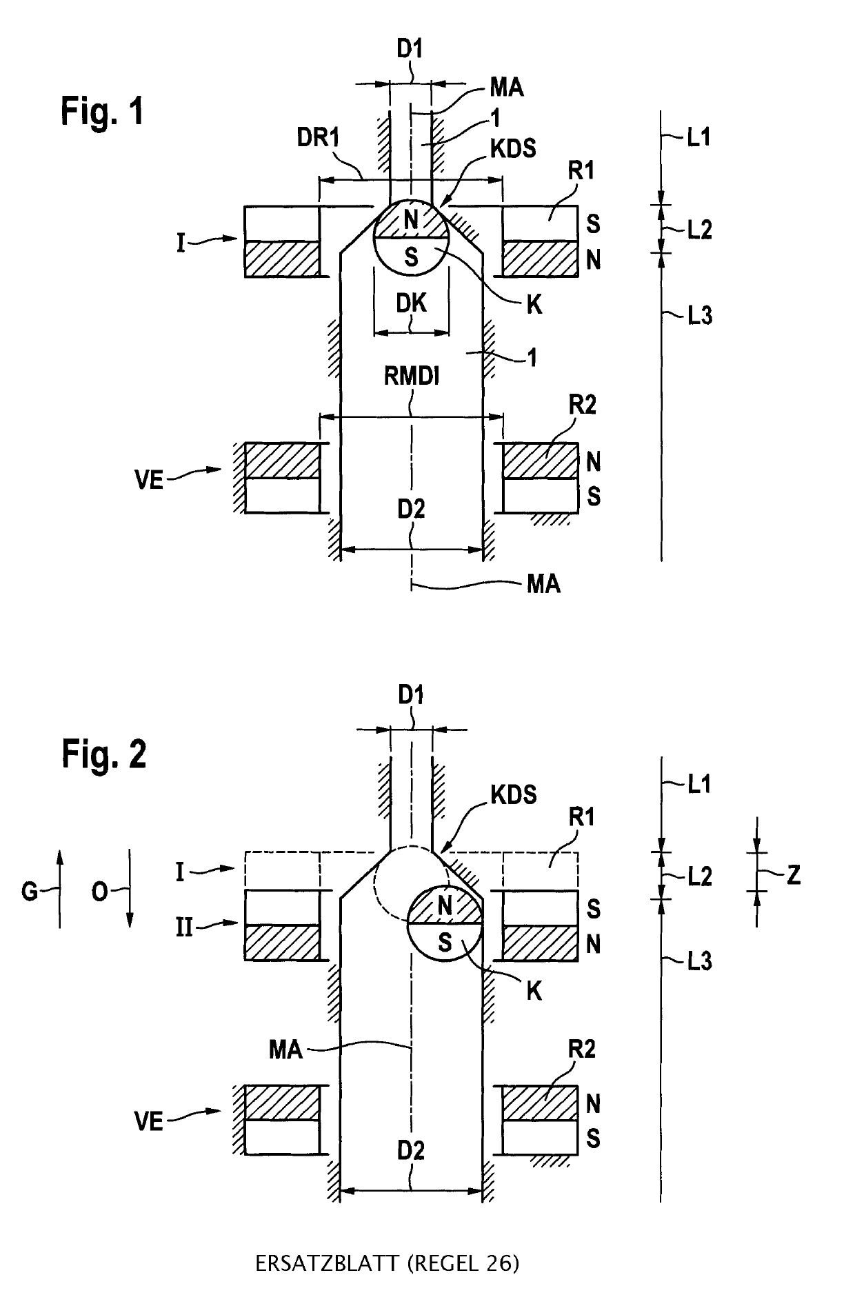
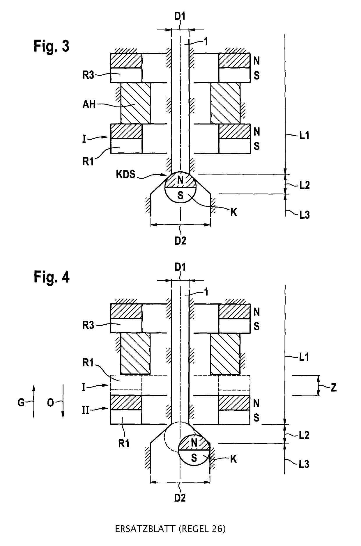
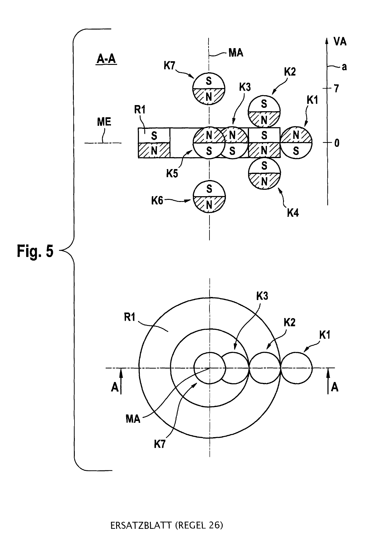
[0054]Note: For the whole description here present, when mentioning magnetic polarizations of magnets which are combined with each other, e.g. a north-south polarization is coupled with a south-north polarization (repulsion), the combination of a south-north polarization with a north-south polarization also applies equivalently. This also applies analogously to the case of combining a south-north polarization with a south-north polarization (attraction) and vice versa.

[0055]The flow control device outlined schematically in FIG. 1 has a flow channel 1 composed of non-magnetic material having a center axis MA. The flow channel 1 is divided into three length segments L1, L2 and L3. The first length segment has a first diameter D1. The second length segment extends in a widening cone to the third length segment L3, wherein the flow channel 1 expands conically from the first diameter D1 to a second diameter D2 in the second length segment L2. A magnetic closing ball K, which is movably a...


PUM


Abstract

A flow control device includes a flow channel composed of non-magnetic material having a center axis, a first length segment having a first diameter, a second length segment, wherein the flow channel expands conically from the first diameter to a second diameter in the second length segment, and a third length segment; a magnetic closing ball, which is movably arranged in the second and third length segments and has a ball diameter that lies between the first and the second diameters; a first, axially polarized (north-south) ring magnet, which is oriented centrally in the center axis and is arranged so as to be longitudinally movable along the center axis and has an inside diameter that is greater than the outside diameter of the flow channel in the third length segment; and a preloading device, which axially pushes the north-south-polarized first ring magnet toward the first length segment.

Description

[0001]This application is a National Stage application of PCT international application PCT / EP2016 / 057822, filed on Apr. 8, 2016 which claims the priority of German Patent Application No. 102015004691.8, filed with the German Patent Office on Apr. 10, 2015, both of which are incorporated herein by reference in their entirety.FIELD OF THE INVENTION[0002]The present invention relates to a flow control device.BACKGROUND OF THE INVENTION[0003]It is not always possible when handling liquids, for example in testing laboratories and during sampling for the purpose of quality control and similar applications, to prevent loss of material due to overflow or overdosing. During filling and decanting operations, liquids are spilled which require cleaning effort that causes more or less problems depending on the quality of the liquids. In general, funnel devices are the customary tools used when decanting. They are available as simple funnels, such as are known from household use, as well as, for...

Claims


Application Information

Patent Timeline
Patent Type & Authority Patents(United States)
IPC IPC(8): F16K31/08B67C11/04B67C11/06B67C3/28
CPCF16K31/084B67C11/04F16K31/086B67C11/06B67C3/28
Inventor HUBNER, PETER
Owner BURKLE GMBH
Why Eureka
Try Eureka