
Calibration method for parallel multi-channel wireless channel measurement and system for the same

a multi-channel wireless and channel measurement technology, applied in the field of wireless communication test technologies, can solve the problems of not being suitable for a high-speed movement scenario, the foregoing algorithm does not radically solve, and the clock jitter error still exists, so as to shorten the calibration time

Inactive Publication Date: 2019-07-23
SHANGHAI RES CENT FOR WIRELESS COMM
View PDF12 Cites 0 Cited by
  • Summary
  • Abstract
  • Description
  • Claims
  • Application Information

AI Technical Summary

Benefits of technology

The present invention allows for better channel measurement in high-speed scenarios by transmitting and receiving data in parallel. Additionally, a calibration transmitting channel and a calibration receiving channel are added to supervise the channel response characteristic in real-time and online, ensuring accurate channel measurements and avoiding measurement errors caused by mutual interference between channels.

Problems solved by technology

However, the calibration solution imposes a quite strict control requirement on synchronous switching of the receiving end and the transmitting end, and generally relates to a relatively long measurement time, and consequently is not suitable for a high-speed movement scenario.
However, in an actual operation process, an error always exists between switching of the switches of the receiving end and the transmitting end, the measurement error is caused because of clock jitters of the receiving end and the transmitting end, and a larger quantity of switching times of the switches indicates a larger introduced clock jitter error.
However, the foregoing algorithm does not radically resolve a time jitter problem caused by switching of the switches, and a clock jitter error still exists during measurement.
Additionally, even if multiplex testing signals transmitted in parallel use an orthogonal sequence, the testing signals still interfere with each other because of different time delays at the receiving end, and calibration precision is affected.

Method used


Image

  • Calibration method for parallel multi-channel wireless channel measurement and system for the same
  • Calibration method for parallel multi-channel wireless channel measurement and system for the same
  • Calibration method for parallel multi-channel wireless channel measurement and system for the same

Examples


Embodiment Construction

[0053]Technical content of the present invention is described in detail below with reference to accompanying drawings and specific embodiments.

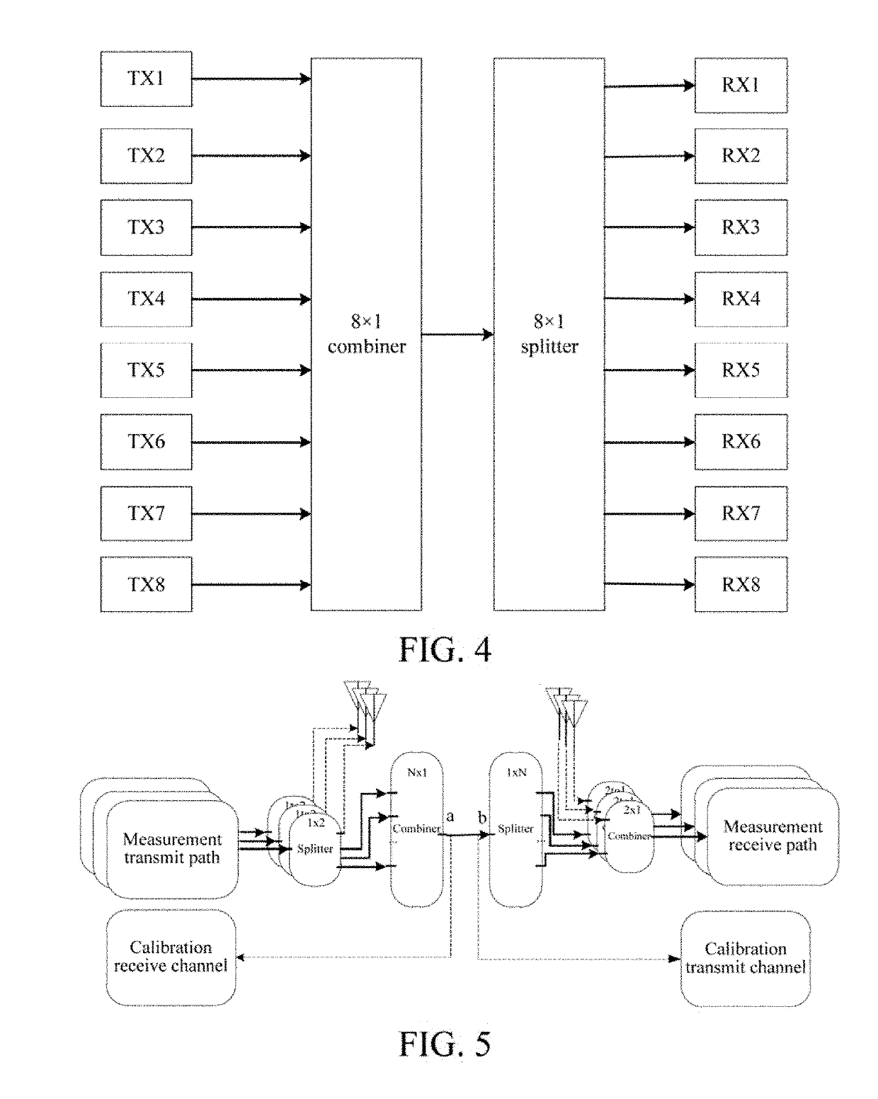
[0054]FIG. 4 is a block diagram showing that eight antenna ports transmit / receive data in parallel according to an embodiment of the present invention. Antennas TX1 through TX8 transmit data simultaneously, and antennas RX 1, RX 2 . . . RX 8 simultaneously receives the data transmitted by TX1 through TX8. In this way, it is not needed to repetitively switch, and a frequency response matrix of transmitting channels and receiving channels could be simultaneously acquired by transmitting once. Compared with a conventional calibration method, calibration data is simultaneously transmitted and received without switching in the present invention, so as to resolve a time jitter problem caused by frequently switching and thus improve measurement precision.

[0055]On the other hand, measurement error is inevitable to some extent. Multi-channel concurren...


PUM


Abstract

The present invention discloses a calibration method for parallel multi-channel wireless channel measurement and a calibration system thereof. The transmitting end and the receiving end are disconnected, and are respectively connected to the calibration receiving channel and the calibration transmitting channel, and the calibration receiving channel / calibration transmitting channel cooperates with a measurement channel in air interface measurement, to calibrate a channel response characteristic of the transmitting end and the receiving end. By means of the present invention, a current channel response characteristic between multiple channels can be online supervised in real time, so as to ensure that a measurement error because of an impact of mutual interference between multiple channels can be avoided in the channel measurement process.

Description

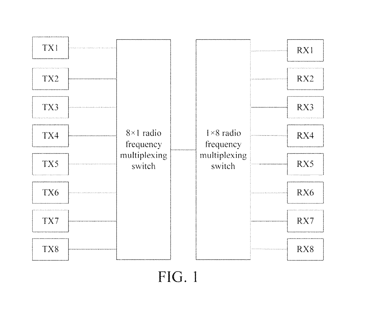
BACKGROUNDTechnical Field[0001]The present invention relates to a calibration method for parallel multi-channel wireless channel measurement, and also to a calibration system for implementing the calibration method, and belongs to the field of wireless communications test technologies.Related Art[0002]In a conventional communications test technology, a calibration solution for a parallel multi-channel wireless channel is basically evolved from a calibration solution in a single-channel scenario. In the calibration solution, multi-channel switching is implemented in dependence on a multiplexing switch to implement multi-channel calibration and measurement, and only one channel is measured at a same moment, and therefore the calibration solution is essentially a measurement and calibration solution based on time division. In the calibration solution, measurement signals do not need to be orthogonal to each other. Therefore, the structure is relatively simple, and system implementation...

Claims


Application Information

Patent Timeline
Patent Type & Authority Patents(United States)
IPC IPC(8): H04W56/00H04B1/69H04B17/21H04B17/14H04B17/00H04J13/18H04B17/30H04J13/00
CPCH04W56/0065H04B1/69H04B17/0085H04B17/14H04J13/18H04W56/001H04B17/21H04J2013/0096H04B17/30H04B1/7113H04J13/004
Inventor CAI, ZHONG-FEIGUI, YUN-SONGWANG, HAO-WENZHOU, MING-TUOYANG, YANGWANG, HAI-FENG
Owner SHANGHAI RES CENT FOR WIRELESS COMM
Learn More