
Air conditioning control method for vehicle

a technology for air conditioning and vehicles, applied in vehicle components, vehicle heating/cooling devices, transportation and packaging, etc., can solve the problems of inefficient use of energy for heating, large loss of energy, and conventional heat sources available for heating the interior of vehicles. , to achieve the effect of reducing the current air flow

Active Publication Date: 2019-07-30
HYUNDAI MOTOR CO LTD
View PDF20 Cites 2 Cited by
  • Summary
  • Abstract
  • Description
  • Claims
  • Application Information

AI Technical Summary

Benefits of technology

The present invention provides a method for controlling air-conditioning in a vehicle to improve heating performance. The method optimizes the operation of the air-conditioning blower based on external air temperature and the amount of time after the engine is started under maximum heating condition and the air-conditioning system is turned on. It determines the reference temperature, compares the interior temperature of the vehicle with the reference temperature, and reduces the current air flow from the air-conditioning blower to warm up the engine if the engine has not been warmed up based on the coolant temperature. The technical effects of the invention are improved heating performance of the vehicle and minimized heat loss during engine warming-up.

Problems solved by technology

Meanwhile, due to recent improvement in the efficiency of engines and multistage of transmissions, conventional heat sources available for heating the interior of vehicles have been insufficient, and there is a need for a technology that can improve heating performance efficiently using the insufficient heat sources.
Further, in order to prevent frost on the inside of windows of a vehicle, an air-conditioning mode is controlled in a ventilation mode, but in this case, the interior air is discharged outside and a large amount of energy is lost.
Therefore, heating is conventionally performed without consideration of the amount of lost energy, and as a result, energy for heating is inefficiently used.
Further, the heat from an engine is used for heating, so the warming-up performance of the engine is reduced due to the loss of energy.

Method used

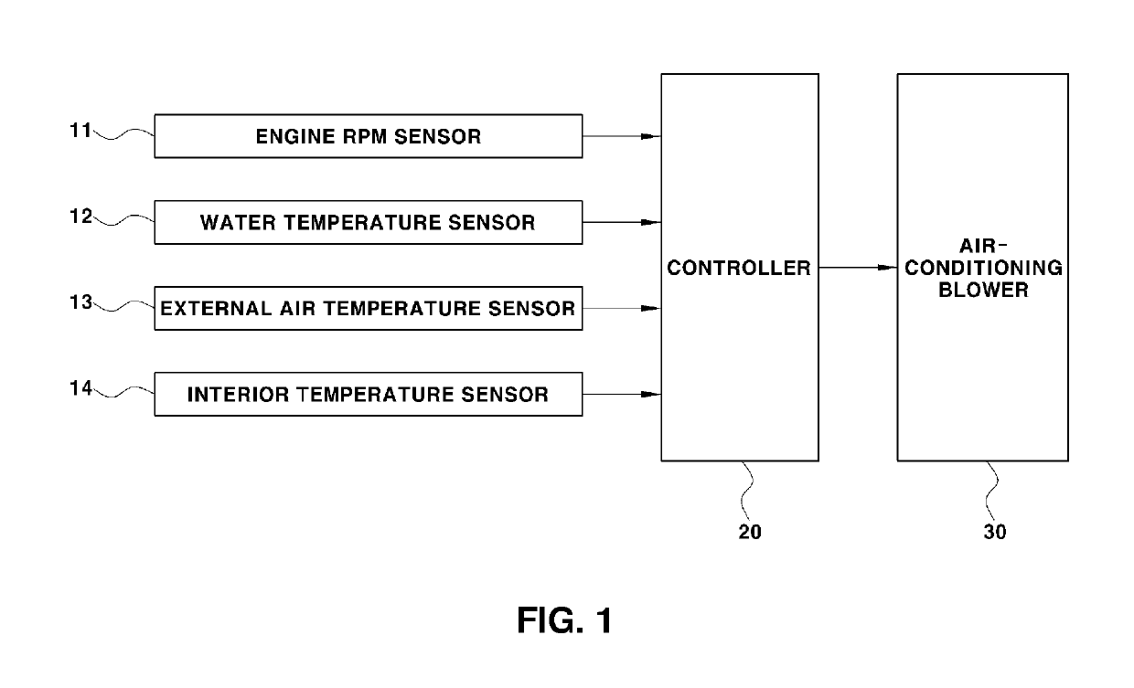
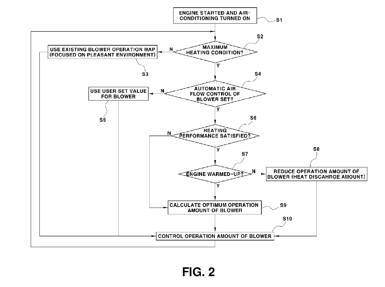
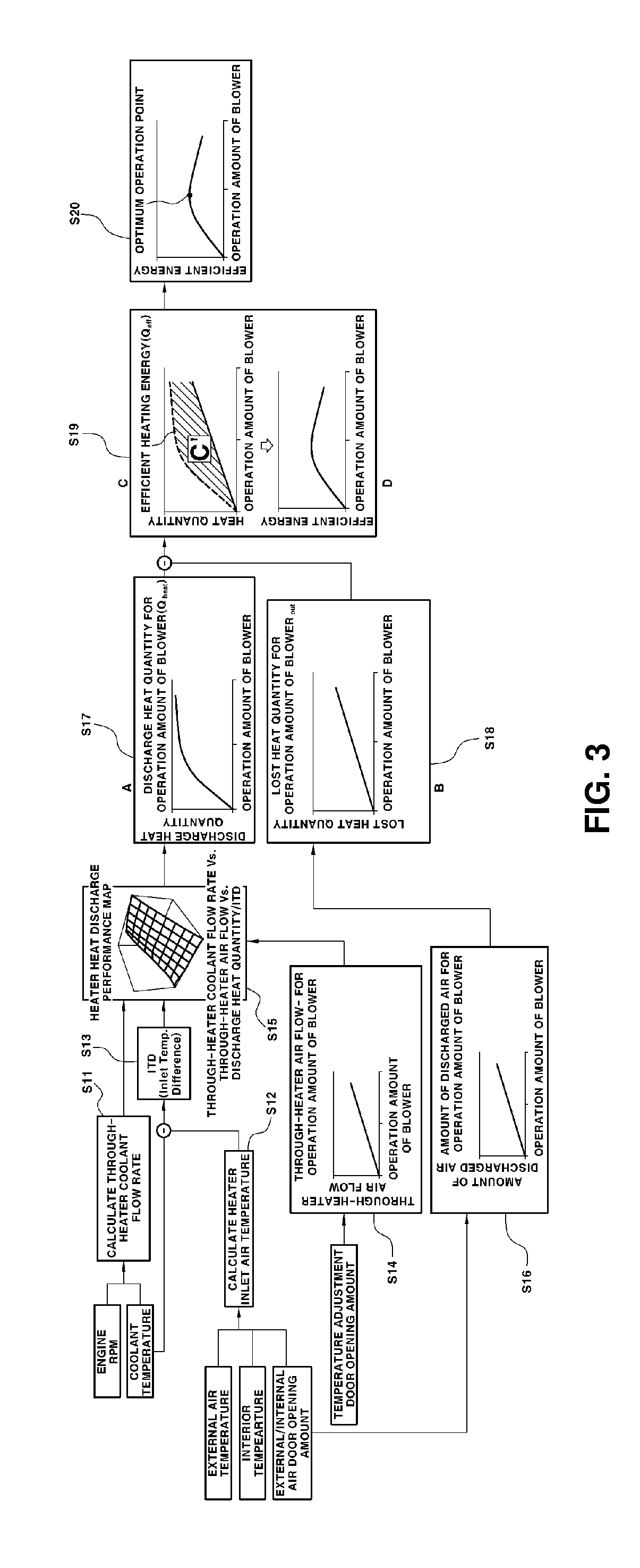

Image

  • Air conditioning control method for vehicle
  • Air conditioning control method for vehicle
  • Air conditioning control method for vehicle

Examples


Embodiment Construction

[0032]Hereinafter reference will now be made in detail to various embodiments of the present disclosure, examples of which are illustrated in the accompanying drawings and described below. While the disclosure will be described in conjunction with embodiments, it will be understood that present description is not intended to limit the disclosure to those embodiments. On the contrary, the disclosure is intended to cover not only the embodiments, but also various alternatives, modifications, equivalents and other embodiments, which may be included within the spirit and scope of the disclosure as defined by the appended claims.

[0033]The terminology used herein is for the purpose of describing particular embodiments only and is not intended to be limiting of the disclosure. As used herein, the singular forms “a,”“an,” and “the” are intended to include the plural forms as well, unless the context clearly indicates otherwise. It will be further understood that the terms “comprises” and / or...


PUM


Abstract

An air-conditioning control method for calculating an optimum operation amount of an air-conditioning blower in an air-conditioning system of a vehicle includes: determining a heater heat quantity after an engine of the vehicle is started under a maximum heating condition of the air-conditioning system and the air-conditioning system is turned on according to current vehicle state information and air-conditioning information; determining a lost heat quantity discharged outside the vehicle during a current air-conditioning mode; determining an effective heating energy efficiency by calculating a difference between the heater heat quantity and the lost heat quantity; calculating the optimum operation amount of the air-conditioning blower where the effective heating energy is maximized; and controlling operation of the air-conditioning blower according to the determined optimum operation amount.

Description

CROSS-REFERENCE TO RELATED APPLICATION[0001]This application claims under 35 U.S.C. § 119(a) the benefit of and priority to Korean Patent Application No. 10-2015-0161468 filed on Nov. 18, 2015, wherein the entire contents of which are incorporated herein by reference.BACKGROUND[0002](a) Technical Field[0003]The present disclosure relates generally to an air conditioning control method for a vehicle and, more particularly, to a method of controlling air-conditioning in a vehicle that can improve heating performance of a vehicle by performing optimal operation amount control.[0004](b) Background Art[0005]Modern vehicles are typically equipped with a Heating, Ventilating, and Air Conditioning (HVAC) system for controlling the interior temperature and creating a pleasant cabin atmosphere. Further, many vehicles are equipped with a Full Automatic Temperature Control (FATC) system that provides a pleasant environment by automatically controlling the interior temperature on the basis of te...

Claims


Application Information

Patent Timeline
Patent Type & Authority Patents(United States)
IPC IPC(8): B60H1/00B60H1/12
CPCB60H1/00735B60H1/00764B60H1/12B60H1/00828B60H1/00885B60H1/00807
Inventor LIM, TAE WOONGPARK, JAE HYUNKWON, CHUN KYUKWON, JUNG HO
Owner HYUNDAI MOTOR CO LTD
Learn More