Supercharge Your Innovation With Domain-Expert AI Agents!

Method and device for indicating the fuel consumption and/or efficiency of a heating unit

a technology for heating units and fuel consumption, applied in the field of heating units, can solve the problems of not being able to deduce the savings from electricity bills, the user (the payer) has few means for comparing the actual performance of the heating unit, and the user (the payer) cannot deduce the ecological footprint of the heating uni

Inactive Publication Date: 2019-07-30
BOOSTHEAT
View PDF11 Cites 0 Cited by
  • Summary
  • Abstract
  • Description
  • Claims
  • Application Information

AI Technical Summary

Benefits of technology

Provides users with clear information on energy consumption and efficiency, enabling them to quantify savings and understand the ecological impact of their heating units, with minimal electric energy demand and no calorie loss in auxiliary cooling systems.

Problems solved by technology

But in the known art, the user of such a heating unit has few means for comparing the actual performance compared to the stated performance and for verifying that the expected savings from the heat pump system are materialized as actual savings.
In particular, the user (the payer) cannot deduce from their electricity bill the savings that they got from the heat pump and has no information on the ecological footprint of their unit.

Method used


Image

  • Method and device for indicating the fuel consumption and/or efficiency of a heating unit
  • Method and device for indicating the fuel consumption and/or efficiency of a heating unit

Examples


Embodiment Construction

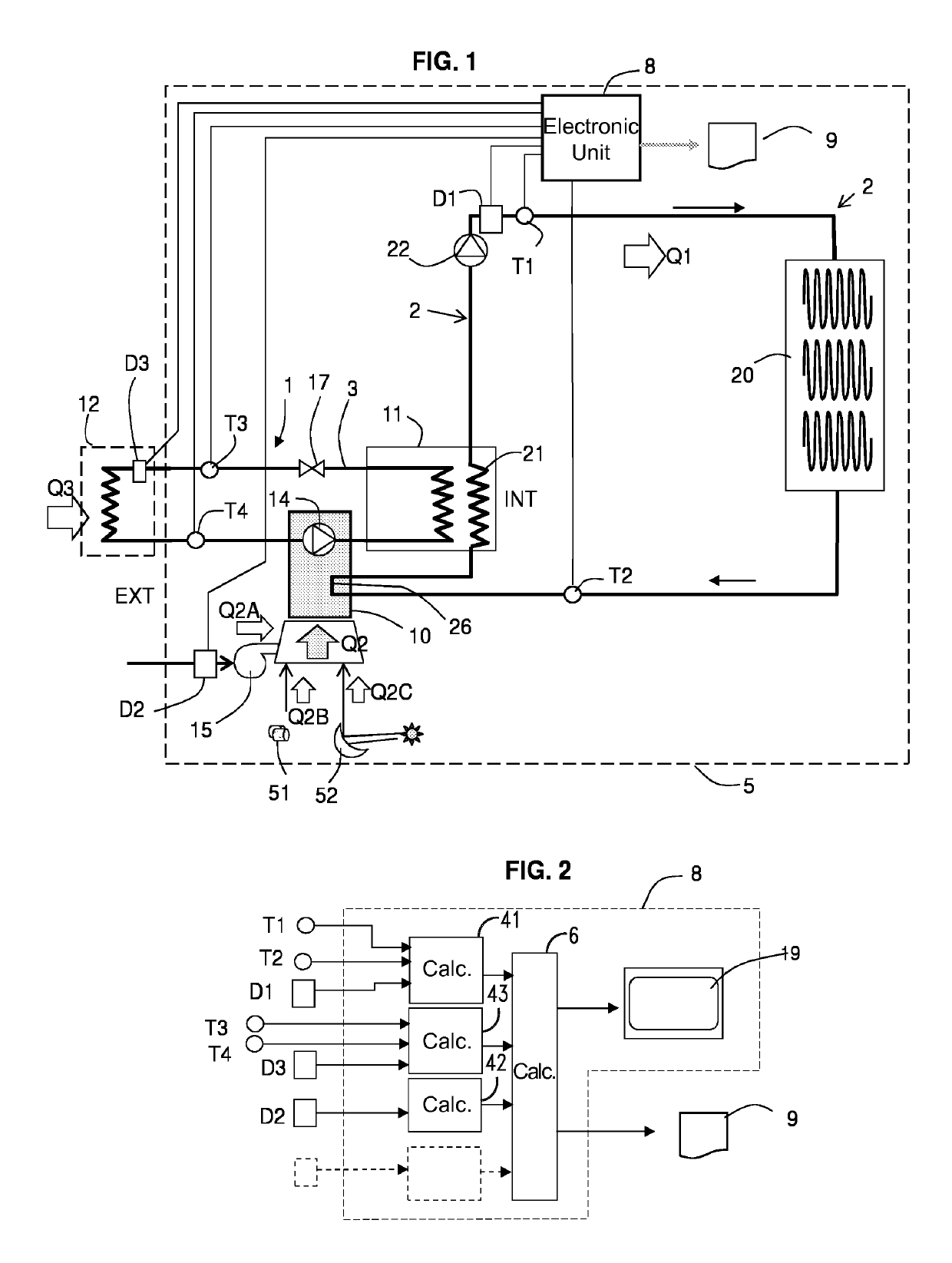
[0036]FIG. 1 schematically shows a heating unit including a heating fluid distribution circuit 2, where the fluid delivers calories to a plurality of receivers-exchangers, of convective or radiative type 20 as known in the state-of-the-art.

[0037]In the shown example, the fluid can be water or an aqueous solution, but the use of air or another fluid for the distribution circuit is not excluded. The receivers-exchangers can take the form of a radiant floor, conventional wall heating radiators or any other type of exchangers serving to deliver calories to the inside of a building 5. The building in question can be an individual house, a shared use building, an industrial building or any other type of room requiring a heating unit. The distribution circuit can also serve several buildings or several rooms. The distribution circuit is a closed circuit; a circulating pump 22 also called ‘circulator’22 delivers a closed loop flow-rate to the heating fluid. The distribution circuit can supp...


PUM

PropertyMeasurementUnit
temperatureaaaaaaaaaa
energyaaaaaaaaaa
combustible meteraaaaaaaaaa

Abstract

A method indicates to a user the fuel consumption and / or efficiency of a heating installation having a heat pump with a thermal compressor, a heating fluid distribution circuit and radiators receiving a first quantity of energy Q1. The method includes the steps: A—of determining, over a predetermined time period a second quantity of energy Q2, corresponding to the supply of heat energy used to drive the compressor, B—of determining, over the same predetermined time period, a third quantity of energy Q3 corresponding to free energy taken from the external environment, C—of displaying the quantities Q2 and Q3, in relation to the predetermined time period, on a display screen and / or in a document for invoicing the customer.

Description

BACKGROUNDTechnical Field[0001]The present invention relates to heating units and to methods and devices for indicating the consumption and / or efficiency of said heating units.[0002]More specifically it concerns a heating unit comprising at least one heat pump, a circuit for heating fluid distribution and a plurality of convectors or radiators.DESCRIPTION OF THE RELATED ART[0003]From the prior art it is known to determine a performance factor (or efficiency factor) for the heat pump in question, in particular the devices using an electric compressor. However, the efficiency factor of such a unit depends on climatic conditions, in particular the outside temperature of the environment in which the calories are gathered. In practice, it is common to add a backup heating device to take over for the heat pump in order to get through cold critical periods.[0004]But in the known art, the user of such a heating unit has few means for comparing the actual performance compared to the stated p...

Claims


Application Information

Patent Timeline
Patent Type & Authority Patents(United States)
IPC IPC(8): G01K17/06G01K17/10F24D19/10G06Q50/06G06Q30/04
CPCG01K17/06F24D19/1048G06Q50/06G01K17/10G06Q30/04
Inventor JACQUET, LUC
Owner BOOSTHEAT
Features
  • R&D
  • Intellectual Property
  • Life Sciences
  • Materials
  • Tech Scout
  • Unparalleled Data Quality
  • Higher Quality Content
  • 60% Fewer Hallucinations
Learn More