Communication connector and communication connector with wires

a technology of communication connectors and wires, applied in the direction of coupling device connections, coupling protective earth/shielding arrangements, electrical appliances, etc., can solve the problems a restricted arrangement space, and achieve the effect of suppressing a reduction of communication quality

Active Publication Date: 2019-07-30
AUTONETWORKS TECH LTD +2
View PDF15 Cites 0 Cited by
  • Summary
  • Abstract
  • Description
  • Claims
  • Application Information

AI Technical Summary

Benefits of technology

[0008]According to this configuration, the second wires are surrounded by the conductive wire holding member while the relative positions of the second wires diagonally arranged in the different wire rows are held. Thus, potentials among the wires are stabilized for the second wires positioned to easily change impedance between the wires and impedance changes of the second wires can be suppressed. The reflection of signals at impedance change points can be suppressed in this way, and therefore a reduction of communication quality can be suppressed.
[0009]Further, the wire holding member is configured to surround the second wires with the dividing members assembled. Thus, an operation of inserting the wires through the wire holding member can be simplified.
[0010]If the plurality of terminals are arranged in a single row in the housing, the communication connector tends to be long in the arrangement direction of the terminals. Thus, an arrangement space is likely to be restricted. On the other hand, according to this embodiment, the wires constitute the plurality of wire rows. Therefore, the communication connector has a compact shape and the arrangement space is less likely to be restricted.
[0011]Each wire row may include a plurality of the second wires adjacent to each other, and each dividing member may include a first wall for partitioning the second wire on an outer side and the outside, and a second wall for partitioning between the adjacent second wires. Thus, impedance changes of the wires can be suppressed by a simple configuration.
[0012]Each wire row may include a plurality of the second wires adjacent to each other. At least one dividing member may include first walls for partitioning the second wire on an outer side and second walls for partitioning between the adjacent second wires in each wire row. Thus, an assembling operation in disposing and assembling the wires between the dividing members can be facilitated.
[0014]The communication connector disclosed in this specification suppresses a reduction of communication quality.

Problems solved by technology

Thus, an arrangement space is likely to be restricted.
The communication connector disclosed in this specification suppresses a reduction of communication quality.

Method used


Image

  • Communication connector and communication connector with wires
  • Communication connector and communication connector with wires
  • Communication connector and communication connector with wires

Examples


first embodiment

[0028]A first embodiment is described with reference to FIGS. 1 to 8.

[0029]A communication connector with wires 10 is installed in a vehicle, such as an electric or hybrid vehicle, and is disposed in a wired communication path between an in-vehicle electrical component (navigation system, ETC, monitor or the like) and an external device (camera or the like) or between in-vehicle electrical components in the vehicle. In the following description, an X direction is a rightward direction, a Y direction is an upward direction and a Z direction is a forward direction.

(Communication Connector with Wires 10)

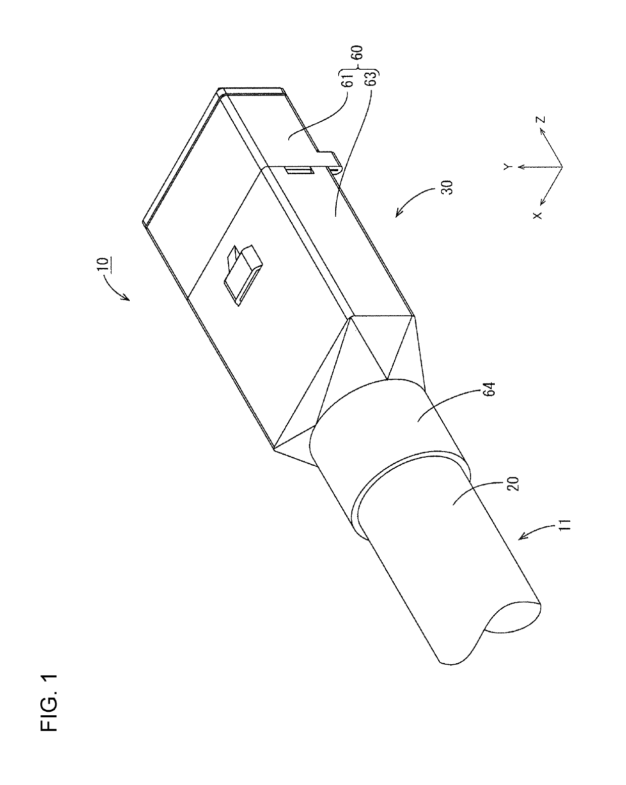
[0030]The communication connector with wires 10 includes, as shown in FIG. 1, a cable 11 and a communication connector 30 provided on an end part of the cable 11.

[0031](Cable 11)

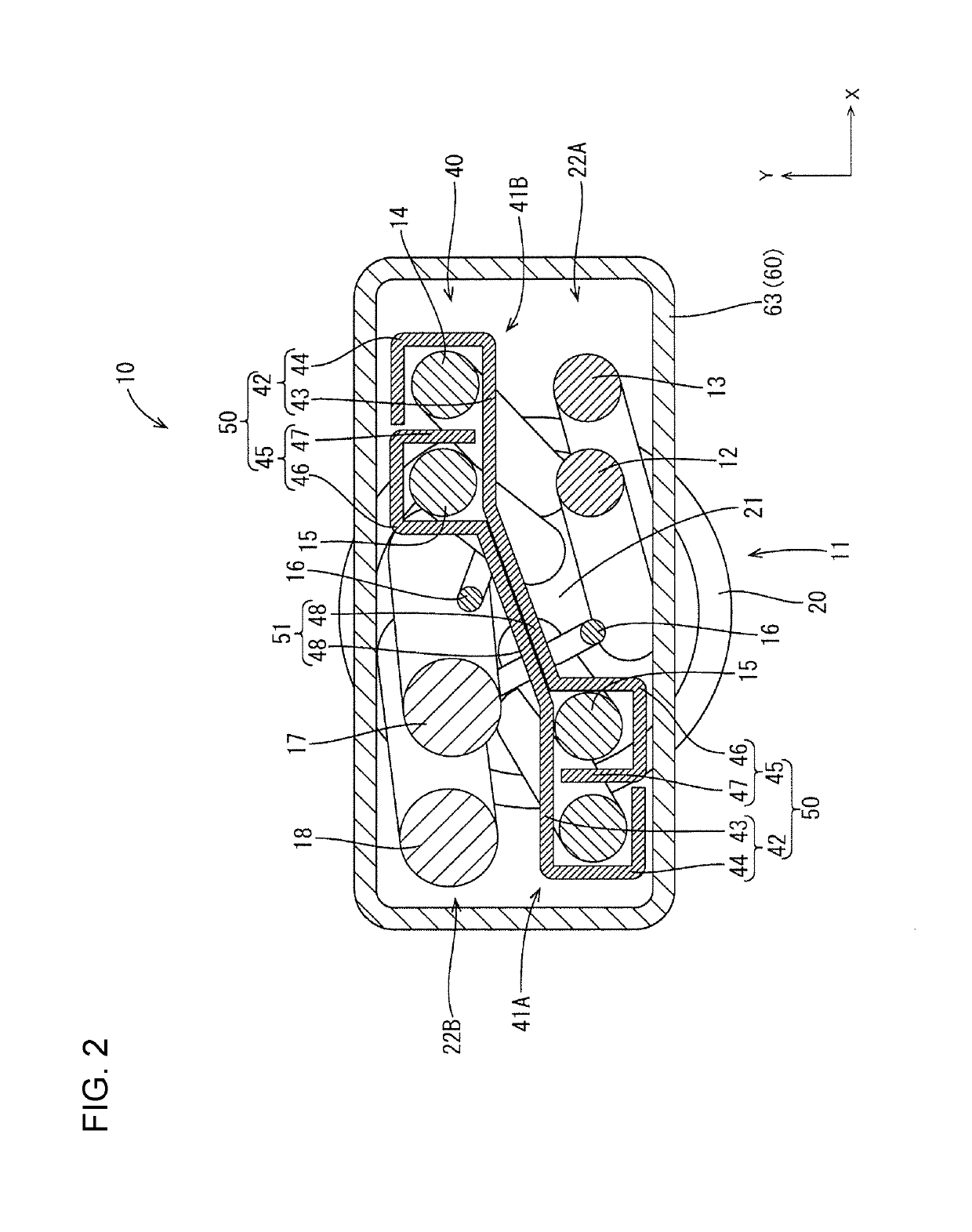
[0032]The cable 11 is capable of high-speed communication of 1 Ghz or faster and includes, as shown in FIG. 2, wires 12 to 18 and an insulating coating 20 for collectively surrounding the wires 12 to 18. A shiel...

case 60

(Shield Case 60)

[0044]The shield case 60 is made of metal, such as aluminum or aluminum alloy and includes, as shown in FIG. 1, a first shield case 61 in the form of a rectangular tube that covers the body 36 of the housing 35 and a second shield case 63 disposed behind the first shield case 61 for covering the wires 12 to 18 and the wire holding member 40. The second shield case 63 is in the form of a box with an open front and includes, on a rear end part, a cylindrical shield connecting portion 64 to be fit externally on the cable 11. The shield connecting portion 64 is, for example, connected to the shield layer folded to the outside of the coating 20 at the end part of the cable 11, such as by welding or crimping. The wire holding member 40 is inserted through the second shield case 63 with a tiny clearance defined therebetween. Thus, the dividing members 41A, 41B are held in an assembled state in the second shield case 63 and their separation is restricted.

[0045]According to t...

second embodiment

[0050]A second embodiment is described with reference to FIGS. 9 to 13.

[0051]In a communication connector of the second embodiment, the shapes of dividing members 71A, 71B in a wire holding member 70 are changed. Since the other components are the same as in the first embodiment, the same components as in the first embodiment are denoted by the same reference signs and not described below.

[0052]The wire holding member 70 is formed by applying stamping and bending to a metal plate material, such as aluminum, aluminum alloy, copper or copper alloy. The wire holding member 70 includes, as shown in FIG. 9, left and right wire accommodating portions 72A, 72B that individually surround two second wires 14, 15 and a coupling 83 coupling the two diagonally arranged wire accommodating portions 72A, 72B. This wire holding portion 70 is composed of two dividing members 71A, 71B, as shown in FIG. 10. One dividing member 71A includes left and right first walls 73A, 73B disposed outside the secon...


PUM


Abstract

A communication connector (30) includes terminals (31) to be connected to wires (12 to 18), including first wires (12, 13) and second wires (14, 15) capable of faster communication than the first wires (12, 13). The wires (12 to 18) form first and second wire rows (22A, 22B). A housing (35) accommodates the terminals (31). A conductive wire holding member (40) holds relative positions of the second wires (14, 15) on one end of the first wire row (22A) in an arrangement direction and the second wires (14, 15) on an opposite end of the second wire row (22B). The wire holding member (40) has dividing members (41A, 41B) configured to surround the second wires (14, 15) when the dividing members (41A, 41B) are assembled.

Description

BACKGROUND[0001]Field of the Invention[0002]This specification relates to communication connectors.[0003]Description of the Related Art[0004]Japanese Unexamined Patent Publication No. 2008-507110 discloses an electrical connector capable of receiving four USB plug connectors. This electrical connector includes a housing, electrical contacts made of L-shaped metal pieces, an outer shield and an inner shield. Electrical contacts are fixed side by side in a lateral direction for each USB plug connector.[0005]A cable may be used as a conductor instead of a metal bar and has wires exposed at an end part of the cable where a coating is removed. Intervals between the wires easily change in this part where the wires are exposed, and impedance change points of the wires are created to reflect signals. Thus, communication quality may be reduced.[0006]This specification discloses a communication connector that suppresses a reduction of communication quality.SUMMARY[0007]A communication connect...

Claims


Application Information

Patent Timeline
Patent Type & Authority Patents(United States)
IPC IPC(8): H01R13/658H01R13/6473H01R9/03H01R13/502H01R13/6582H01R13/6592
CPCH01R13/6473H01R13/6592H01R13/6582H01R13/502H01R13/65915
Inventor MATROJA, RHUSHIK
Owner AUTONETWORKS TECH LTD
Why Eureka
Try Eureka