Thermal conducting structure
a conducting structure and conducting technology, applied in the direction of conduction heat transfer modifications, lighting and heating apparatus, cooling/ventilation/heating modification, etc., can solve the problems of unvalued thermal management of electronic products, unfavorable thermal management, and worse operating environment of ic chips, etc., to achieve low spreading resistance, simple and easy manufacturing method of direct sintered metal mesh, and low cost
- Summary
- Abstract
- Description
- Claims
- Application Information
AI Technical Summary
Benefits of technology
Problems solved by technology
Method used
Image
Examples
first embodiment
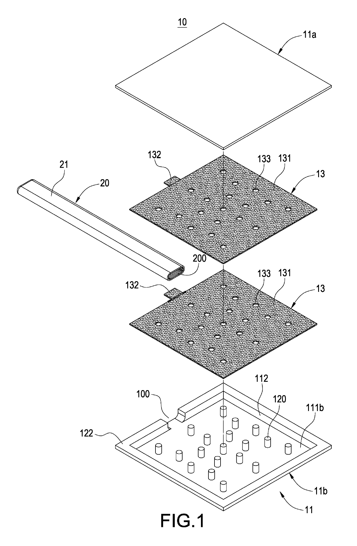
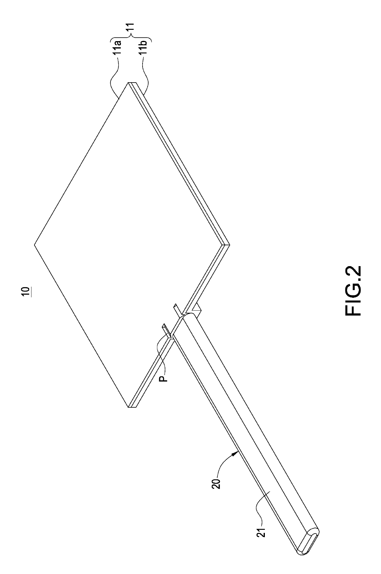
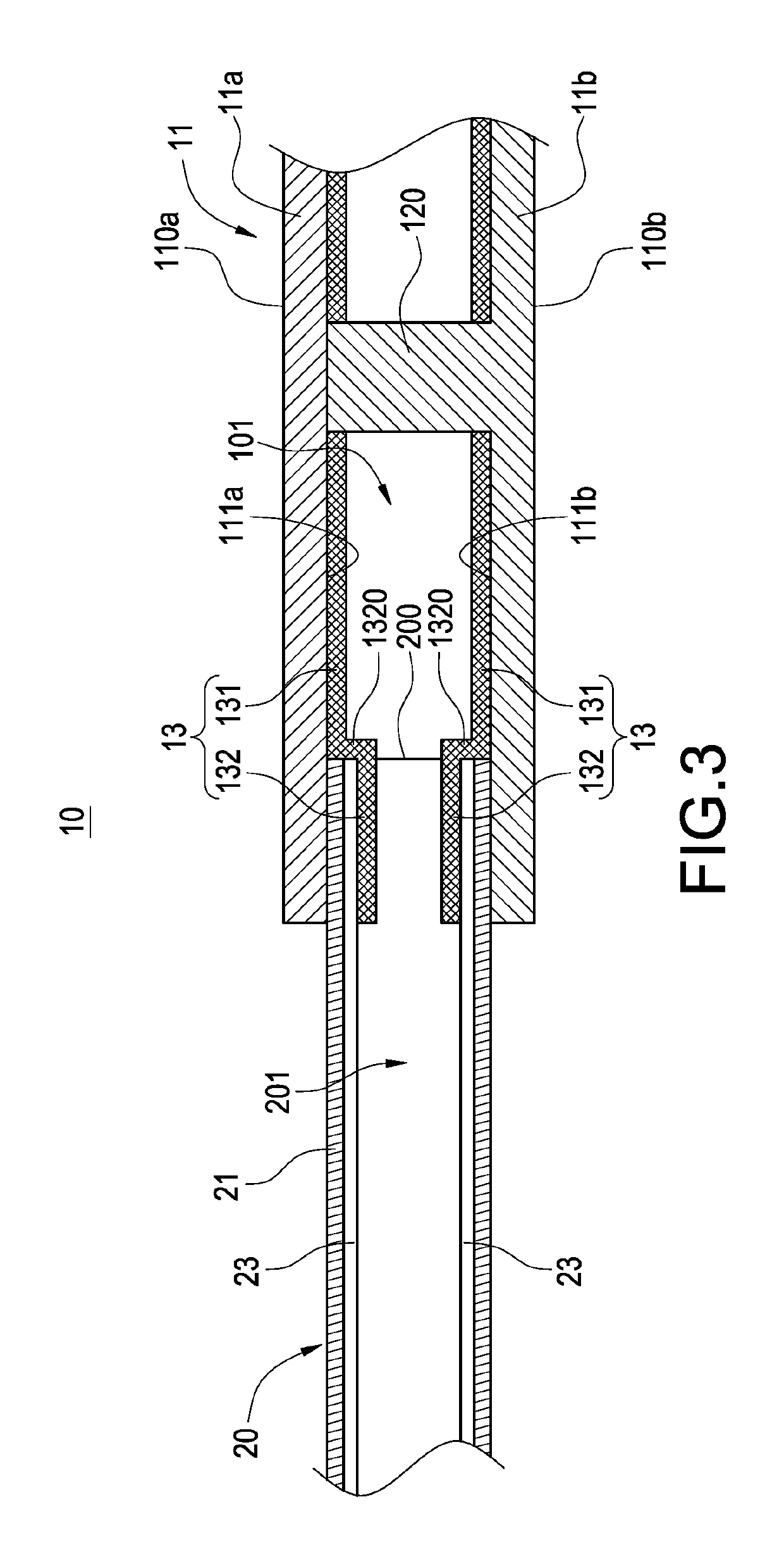
[0021]With reference to FIGS. 1 to 3 for a thermal conducting structure in accordance with this disclosure, the thermal conducting structure comprises a vapor chamber 10 and at least one heat pipe 20 coupled to the vapor chamber 10.
[0022]The vapor chamber 10 includes a casing 11 and at least one through hole 100 formed on a side of the casing 11, and the casing 11 is formed by engaging a first casing member 11a and a second casing member 11b by a stamping, forging or machining method to form a sealed casing 11, and the first or second casing has a fence portion 122 to define a chamber 101 in the vacuum interior of the casing 11, and the chamber 101 is communicated with the through hole 100 and provided for flowing a working fluid (not shown in the figure), and the top, bottom and the periphery of the chamber 101 have an inner top wall 111a, an inner bottom wall 111b and an inner peripheral wall 112, and the through hole 100 is disposed on a side of the casing 11. In other words, the...
second embodiment
[0026]With reference to FIG. 4 for a capillary member of a thermal conducting structure in accordance with this disclosure, the main difference between this embodiment and the previous embodiment resides on the different capillary structures of the casing 11 and the tubular body 21.
[0027]In this embodiment, a metal mesh 24 is covered onto an inner wall of the cavity 201 of the tubular body 20, and a capillary member 14 is covered onto the chamber 101 of the casing 11, wherein the metal mesh 24 is passed through the opening 200 and coupled to the capillary member 14, and the metal mesh 24 is made of a sintered copper powder and attached around the inner wall of the tubular body 21 in form of a copper mesh structure by directly sintering the copper mesh or a diffusion bonding method, and the metal mesh 24 is made of a material including but not limited to copper, aluminum, and stainless steel. In this embodiment, the method of directly sintering the copper mesh to form the capillary s...
PUM
 Abstract
Description
Claims
Application Information
 - R&D
- Intellectual Property
- Life Sciences
- Materials
- Tech Scout
- Unparalleled Data Quality
- Higher Quality Content
- 60% Fewer Hallucinations
Browse by: Latest US Patents, China's latest patents, Technical Efficacy Thesaurus, Application Domain, Technology Topic, Popular Technical Reports.
© 2025 PatSnap. All rights reserved.Legal|Privacy policy|Modern Slavery Act Transparency Statement|Sitemap|About US| Contact US: help@patsnap.com


