
Signature tuning filters

a filter and signature technology, applied in the field of signature tuning filters, can solve the problems of restricting the user's ability to manipulate the outgoing sound, restricting the user's ability to continue to use the filter, and limiting the use of preset filters

Inactive Publication Date: 2019-08-06
OM AUDIO
View PDF17 Cites 0 Cited by
  • Summary
  • Abstract
  • Description
  • Claims
  • Application Information

AI Technical Summary

Benefits of technology

The present invention provides a method and device for providing audio information to an audio output device. The method involves receiving audio filter settings and audio data in a client device, converting the audio filter settings to a time-varying signal, and transmitting the converted signal to the audio output device. The audio output device then modifies the audio data according to the audio filter signal to create a continuous audio output. The technical effect of this invention is to provide a more precise and flexible method for filtering audio signals in real-time, allowing for better control and modification of the audio signal.

Problems solved by technology

Some client devices can apply an audio filter but it is typically limited to preset filters based on a style of music (e.g., rock, pop and classical).
In other instances, a client device allows the user to create a user-defined filter, however, limited functionality may restricts the user's ability to manipulate the outgoing sound.
Moreover, the user cannot continue to use the filter when the user disconnects the client device from the audio output device.
As such, the user cannot continue to use the filter if the user uses another client device
In certain instances, however, music streaming services may prevent the music content from its services from being manipulated by a third-party software application.
In addition, the user cannot continue to use the filter when the user disconnects the client device from the audio output device.
Therefore, there is no way to apply filters to a client device DSP to generate high quality sound on an audio output device.

Method used


Image

  • Signature tuning filters
  • Signature tuning filters
  • Signature tuning filters

Examples


Embodiment Construction

[0026]In the following description, numerous specific details are set forth in order to provide a thorough understanding of the present arrangements and teachings. It will be apparent, however, to one skilled in the art that the present arrangements and teachings may be practiced without limitation to some or all of these specific details. In other instances, well-known process steps have not been described in detail in order to not unnecessarily obscure the primary features of the present arrangements and teachings.

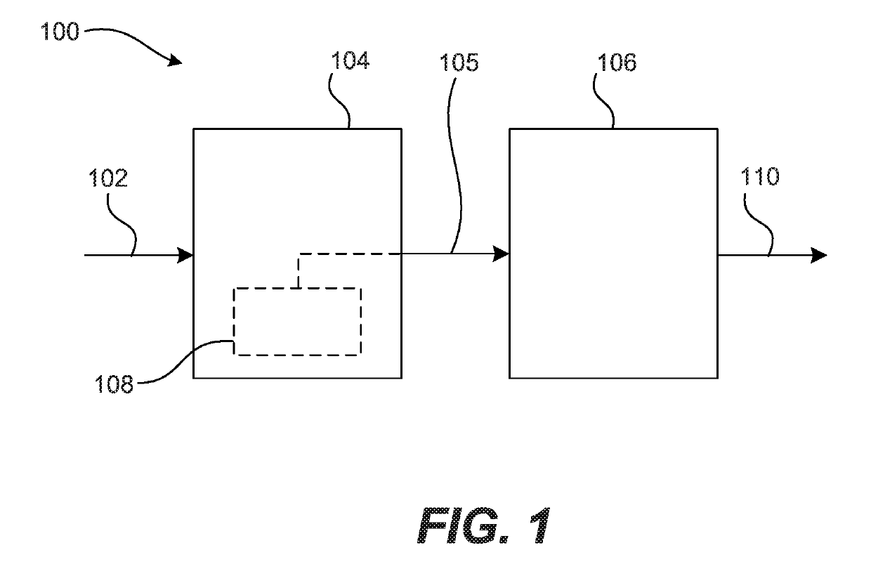
[0027]The present arrangements generally relate to the modification of audio data by audio processing. Those skilled in the art will understand that there are numerous techniques to manipulate audio data. By way of example, audio processing may use one or more audio filters (e.g., biquad, parametric, semi-parametric, high and low pass and graphical) to modify an audio signal. For ease of understanding, audio filter settings will be used to describe audio processing. Howe...


PUM


Abstract

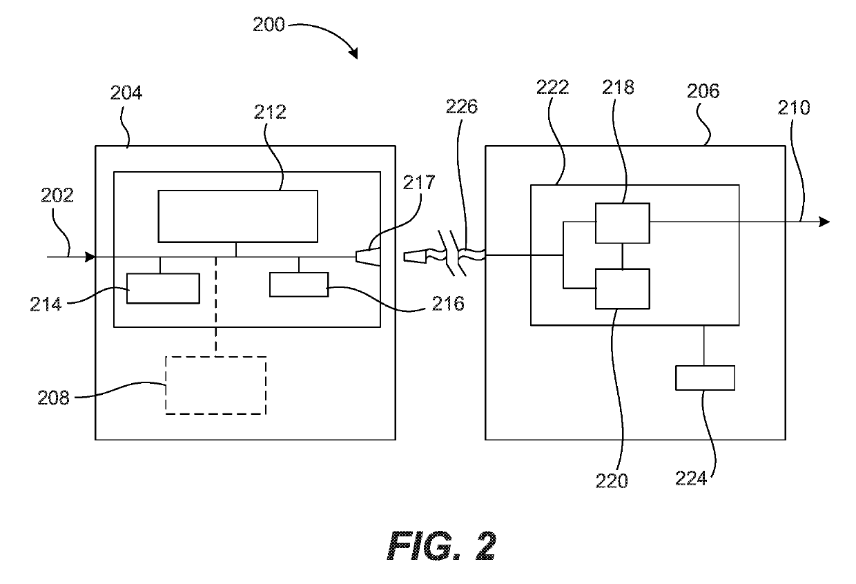
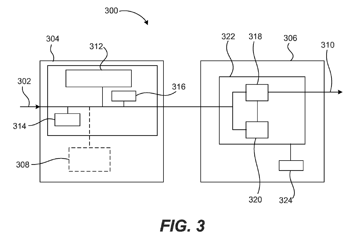
A method of providing audio information, said method comprising: (i) receiving audio filter settings in a client device; (ii) receiving audio data in the client device, wherein the received audio data is in an audio coding format; (iii) converting the audio filter settings to an audio filter signal in a processor of the client device, where the audio filter signal is a time-varying signal; (iv) converting the received audio data to an audio signal in a processor of the client device, where the audio signal is a time-varying signal; and (v) transmitting the converted audio filter signal and the converted audio signal from the client device to an audio output device, where the audio output device is separate from and in communication with the client device, and where the audio output device is configured for modifying the audio signal according to the audio filter signal to generate a time-varying audio output.

Description

RELATED APPLICATION[0001]The application claims priority from U.S. Provisional Application having Ser. No. 61 / 903,888, filed on Nov. 13, 2013, which is incorporated herein by reference for all purposes.FIELD OF THE INVENTION[0002]The present teachings generally relate to audio signal processing. More particularly, the present teachings relate to transmitting audio filter settings to an audio output device wherein the audio output device applies the audio filter settings to audio data.BACKGROUND OF THE INVENTION[0003]The popularity of high-end audio output devices, such as headphones and headsets, has encouraged users to pursue better listening experiences. One method of enhancing the listening experience is to modify the sound produced by an audio output device. This may be accomplished by using an audio filter, which manipulates audio data as it passes through a digital signal processor (hereinafter a “DSP”). Some client devices can apply an audio filter but it is typically limited...

Claims


Application Information

Patent Timeline
Patent Type & Authority Patents(United States)
IPC IPC(8): H04R5/033H04R3/04G10L19/16G06F3/16H04S7/00H04S3/00G10L19/008
CPCH04R3/04G06F3/165G10L19/173H04S7/307H04S3/008H04S2420/03G10L19/008G10L21/02
Inventor DEVILLEZ, DAVIDCONREY, JAMES
Owner OM AUDIO
Learn More