Squeegee with seal flap

a squeegee and seal technology, applied in the field of squeegee assembly, can solve the problems of dirty water and surfactant left behind on the floor, squeegees will partially or wholly lose contact with the floor, etc., to reduce or eliminate the loss of vacuum performance, reduce or eliminate the loss of vacuum pressure, and improve the vacuum performance of the squeegee assembly

Active Publication Date: 2019-08-13
MIDWEST RUBBER SERVICE & SUPPLY CO
View PDF20 Cites 0 Cited by
  • Summary
  • Abstract
  • Description
  • Claims
  • Application Information

AI Technical Summary

Benefits of technology

[0027]During normal operation, the seal flap will be drawn, by engagement with the surface to be cleaned, to an open position that will allow air, dirty water and surfactant to enter the vacuum chamber through the front squeegee channels. However, if the front squeegee lower edge loses contact with the floor due to uneven floor conditions (such as tiles with deep or wide grout lines), the seal flaps will close partially or completely to reduce or eliminate loss of vacuum pressure to the vacuum chamber. Thus, vacuum performance of the squeegee assembly is improved over uneven surfaces by the seal flap acting as a valve that closes when the squeegee lower edge breaks from the floor, to reduce or eliminate loss of vacuum performance. The squeegee assembly of the present invention also increases the life expectancy of the squeegees since the squeegees can maintain a seal with a floor over a greater period of use / time.

Problems solved by technology

Thus, when a scrubber-drier floor cleaning machine traverses over an uneven floor surface (example: grouted tile), the squeegees will partially or wholly lose contact with the floor.
This causes a loss of vacuum pressure due to the additional volume of air entering the vacuum chamber due to a seal break between the uneven floor surface and the generally linear surfaces of the squeegee lower edges.
The result is that dirty water and surfactant are left behind on the floor.
Additionally, as the front squeegee wears, the overall water pick-up performance of the scrubber-drier machine will degrade until total failure of the squeegee, again due to a breakdown of the seal created between the squeegee and the floor.
None of this prior art has resulted in a satisfactory squeegee assembly that has the ability to allow dirty water and surfactant to enter the vacuum chamber and still provide an adequate seal between the squeegee and the floor, particularly on an uneven surface.

Method used


Image

  • Squeegee with seal flap
  • Squeegee with seal flap
  • Squeegee with seal flap

Examples


Embodiment Construction

[0039]For a thorough understanding of the present disclosure, refer to the following detailed description, including the appended claims, in connection with the above-described drawings. Although the present disclosure is described in connection with exemplary embodiments, the present disclosure is not intended to be limited to the specific forms set forth herein. It is understood that various omissions and substitutions of equivalents are contemplated as circumstances may suggest or render expedient, but these are intended to cover the application or implementation without departing from the spirit or scope of the claims of the present disclosure. Also, it is to be understood that the phraseology and terminology used herein is for the purpose of description and should not be regarded as limiting.

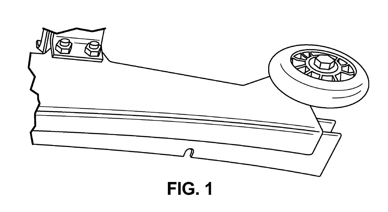
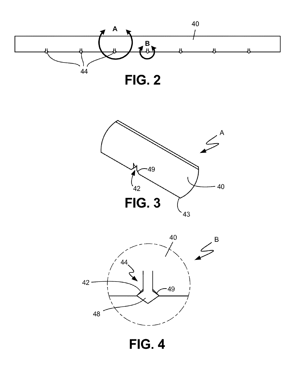
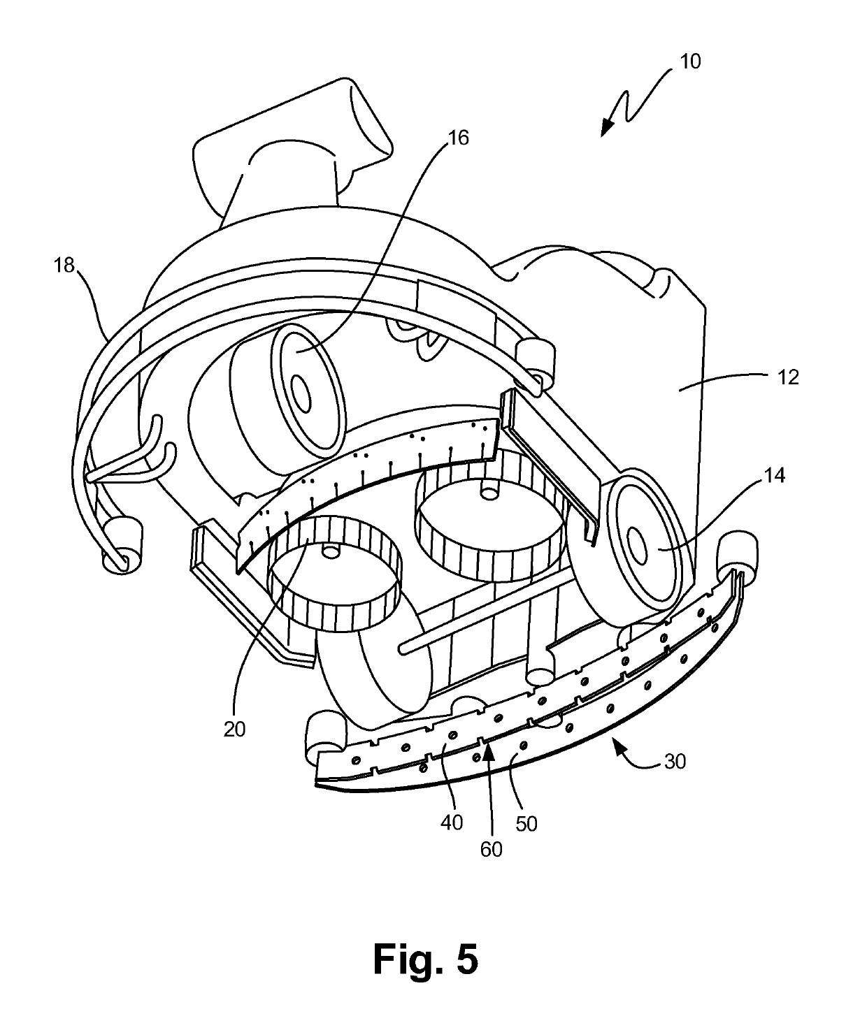
[0040]Although the present invention is designed for many uses, for exemplary purposes only, the invention is described herein as a squeegee assembly for a scrubber-drier floor cleaning mac...


PUM


Abstract

The present invention relates generally to a surface cleaning squeegee assembly and more specifically to a squeegee assembly mounted on a scrubber-dryer floor cleaning machine. The squeegee assembly includes a front squeegee having a number of spaced channels along a lower edge covered by seal flaps, and a rear squeegee having no channels. The front and rear squeegees define a vacuum chamber between them. Air, dirty water and surfactant are vacuumed into the vacuum chamber through the front squeegee channels for ultimate disposal. When the scrubber-dryer surface cleaning machine traverses over an uneven surface, the seal flaps close the channels to limit or eliminate any vacuum loss to the vacuum chamber.

Description

CROSS REFERENCE TO RELATED APPLICATION[0001]This application claims priority to U.S. Provisional Application 62 / 210,003 filed on Aug. 26, 2015, which is hereby incorporated by reference in its entirety.FIELD OF INVENTION[0002]The present invention relates generally to a scrubber-dryer surface cleaning machine and more specifically to a squeegee assembly mounted on a scrubber-dryer floor cleaning machine. The squeegee assembly defines a vacuum chamber between a front and rear squeegee. The squeegees form a partial seal with a surface to be cleaned, such as a floor. Dirty water and surfactant mixture from the cleaning process is directed to the vacuum chamber and the dirty water is drawn by a vacuum from the vacuum chamber to a dirty water tank for subsequent disposal.BACKGROUND OF THE INVENTION[0003]In the global floor care industry, scrubber-drier floor cleaning machines apply water and surfactant to floors, loosen dirt and debris with brushes or pads, and remove the suspended soils...

Claims


Application Information

Patent Timeline
Patent Type & Authority Patents(United States)
IPC IPC(8): A47L11/40A47L11/30A47L11/20
CPCA47L11/4044A47L11/201A47L11/4083A47L11/4016A47L11/305
Inventor ANDERSON, BRENTMEIJDAM, A.L.F.
Owner MIDWEST RUBBER SERVICE & SUPPLY CO
Why Eureka
Try Eureka