Myoelectric prosthesis and method

a myoelectric prosthesis and prosthesis technology, applied in the field of medical devices, can solve the problems of many persisting limitations, limited advanced prosthetics, and primarily cosmetic appearance of passive devices with limited functional benefits, and achieve the effect of limiting cross-talk and greater functional capabilities

Active Publication Date: 2019-08-13
GASTON GLENN +1
View PDF2 Cites 3 Cited by
  • Summary
  • Abstract
  • Description
  • Claims
  • Application Information

AI Technical Summary

Benefits of technology

[0020]In another aspect of the invention, the volar plate and flexor sheath of each amputated digit is transferred dorsally to serve as an interpositional autograft material between the transferred muscles and prevent unwanted cross-talk. Alternatively, an allograft interpositional material may be used.
[0024]In another aspect of the invention, the deeper muscles of the forearm can be transferred into a more superficial location along with their neurovascular pedicles to allow multiple new signal detection and thus an array of new functional options. This includes the flexor digitorum superficialis or profundus for digital flexion. This can be done as a unit for composite grasp, or separately to allow individual digital flexion. This also includes the flexor pollicis longus transfer for independent thumb flexion. This also includes the flexor carpi radialis or flexor carpi ulnaris for wrist flexion. This also includes the flexor carpi ulnaris or extensor carpi ulnaris for ulnar deviation. This also includes the extensor carpi radialis longus or brevis for wrist extension. This also includes the pronator teres or pronator quadratus for pronation. This also includes the extensor digitorum communis, extensor indicis proprius, and extensor digiti quinti for finger extension. This also includes the extensor pollicis longus for thumb extension. Adipofascial flaps or allograft should be used as an interpositional material to limit cross-talk between the individual muscles.
[0025]In another aspect of the invention, any of the muscles listed in the above paragraph from the forearm can be transferred above the elbow to allow a greater number of signals available for detection and greater functional capabilities for above elbow amputees.

Problems solved by technology

Passive devices are primarily for cosmetic appearance with limited functional benefit.
The advent of myoelectric prostheses has revolutionized the field of upper extremity prosthetics, but there are many persisting limitations.
Despite this, these advanced prosthetics are limited by the human-prosthesis interface.
Because of the limited number of muscles available to serve as independent signals for the fingers, individual digital control with myoelectric prostheses has not been possible for patients with partial or total hand amputations.
The lack of available muscle signals has limited the functional ability for patients with partial hand amputations, total hand amputations, below elbow amputations, above elbow amputation, and shoulder disarticulations.
Currently there are limited control options for individuals that have undergone a partial hand amputation.
Clinically this is not preferred since independent and intuitive control is not provided due to the lack of available EMG signals from appropriate muscle groups.
While forearm musculature produces reliable signals, prosthetic control is not natural as the muscle contraction is not associated with the desired prosthetic finger motion.
For below elbow amputations at the level of the forearm, amputees have been limited in achieving all of the normal degrees of freedom possible for the wrist, forearm and hand function due to the limited EMG inputs available to control the desired degrees of freedom.
Basic options such as grasp and release are possible, but control of functions such as radial deviation, ulnar deviation, wrist flexion, wrist extension, pronation and supination have not been possible due the limited number of EMG signals available.
Independent control of the thumb and fingers has also not been possible due to inadequate signals available for detection.
The limitation of this technique is the inability to preform multiple planes of motion simultaneously and independently.
An additional limitation in optimal control of a myoelectric prosthetic is cross-talk.
Cross-talk occurs when multiple muscles are producing multiple signals simultaneously thus making detection of one specific signal difficult.
The largest current limitation of myoelectric prostheses for upper extremity amputees centers on the need for a greater number of available myoelectric signals.

Method used


Image

  • Myoelectric prosthesis and method
  • Myoelectric prosthesis and method
  • Myoelectric prosthesis and method

Examples


Embodiment Construction

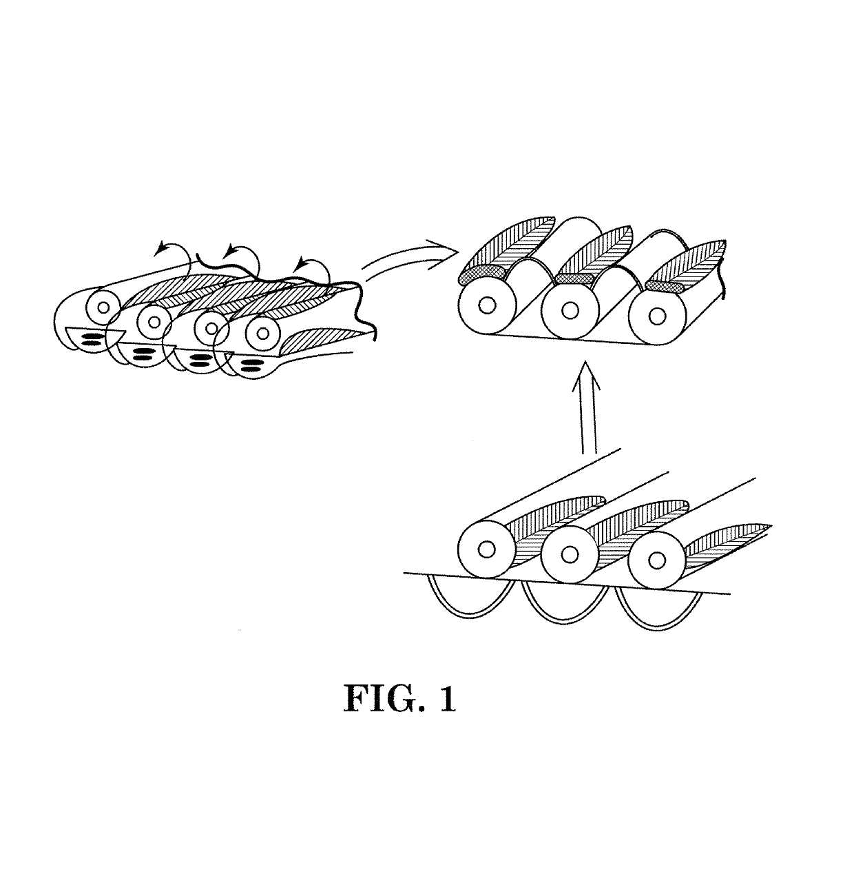
[0032]In describing the invention herein, an understanding must be made that this invention is a surgical technique without which a new generation of prosthetics would not be possible. Those prosthetists adept in upper extremity prosthetics will have unparalleled new functional degrees of freedom to offer patients that have undergone surgeries using the techniques described in this invention. While some newer prosthetic designs may be required such as: multichannel microprocessors, multiple motor drivers, multiple EMG inputs, new more powerful or longer lasting power systems, new housing units for the electronic components, new socket designs, and some new componentry to allow these new degrees of freedom, the requisite for all of this is the invention of the surgical technique to provide the necessary signals for detection.

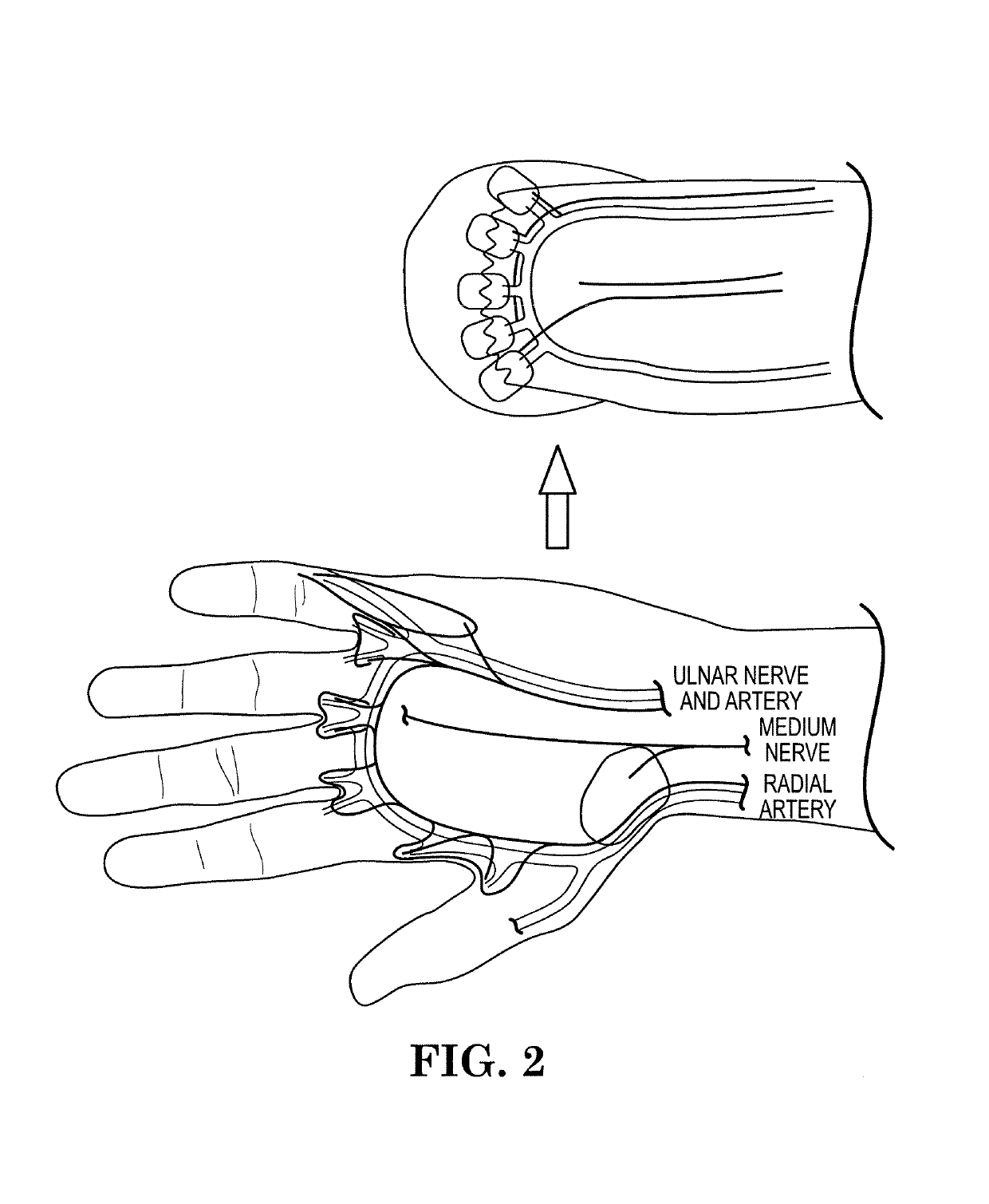
[0033]For partial hand amputations, we have demonstrated that the transfer of the interossei muscles to the dorsum of the hand can provide the necessary signals ...


PUM


Abstract

A method of transferring intrinsic hand muscles along with a respective nerve and blood supply; and allowing signal detection by a surface electrode is provided. The method further includes transferring muscles of a forearm along with a respective nerve and blood supply; and allowing signal detection by a surface electrode.

Description

CROSS REFERENCE TO RELATED APPLICATIONS[0001]This application claims the benefit of U.S. provisional application Ser. No. 62 / 415,872, filed on Nov. 1, 2016; the entirety of which is incorporated by reference herein.FIELD OF THE INVENTION[0002]This invention relates to medical devices with surface electrodes for detecting signals produced by muscles thus allowing prosthetic control (referred to from this point forward in this application as myoelectric prosthesis). Specifically, this application refers to a method of muscle and nerve transfers to allow new signals to be detected by surface electrodes and allow additional myoelectric inputs for myoelectric prostheses.BACKGROUND OF THE INVENTION[0003]There are several types of prostheses available for upper extremity amputees including passive devices, body powered devices and myoelectric devices. Passive devices are primarily for cosmetic appearance with limited functional benefit. Body powered devices require the use of the shoulder ...

Claims


Application Information

Patent Timeline
Patent Type & Authority Patents(United States)
IPC IPC(8): A61B5/00A61F2/58A61F2/72A61B5/0488A61B5/0492A61F2/76A61B5/296
CPCA61F2/72A61B5/6806A61B5/6825A61F2/583A61F2002/7615A61B5/0492A61B5/6826A61B5/296
Inventor GASTON, GLENNLOEFFLER, BRYAN
Owner GASTON GLENN
Why Eureka
Try Eureka