Retaining apparatus
a technology of retaining apparatus and retaining rod, which is applied in the direction of atomized substances, disinfection, packaging, etc., can solve the problems of reducing the operability of the dispenser, user dissatisfaction with the experience or the malfunction, and using unapproved or improper refills in the dispenser
- Summary
- Abstract
- Description
- Claims
- Application Information
AI Technical Summary
Benefits of technology
Problems solved by technology
Method used
Image
Examples
first embodiment
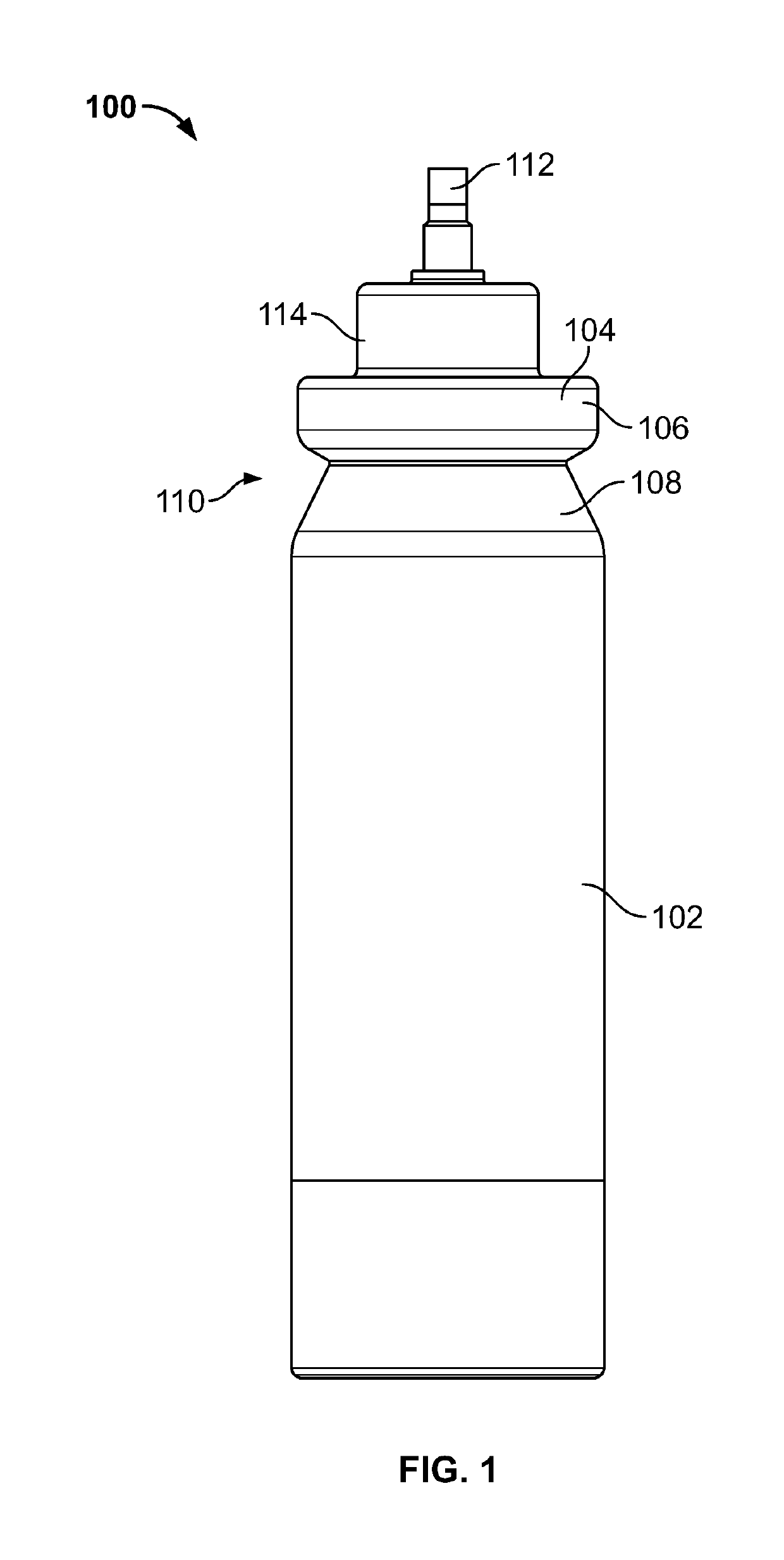
[0046]Referring to FIGS. 4, 5, 7 and 14, a retaining apparatus 216 is shown retaining the aerosol container 100. The retaining apparatus 216 includes a lower portion 218 with a flange 220 extending radially outward therefrom. In the present embodiment, the flange 220 rests on an upper end of the cylindrical wall 212 to hold the container above the base plate 210. Retaining tabs 222 extend radially inward from the lower portion 218 of the retaining apparatus 216. The retaining tabs 222 are configured to hold the aerosol container 100 within the retaining apparatus 216 by snapping into the retaining notch 110, as best seen in FIG. 5. The retaining apparatus 216 and the sealing cap 104 are dimensioned so that the lower rim 106 of the sealing cap 104 is immovably retained between the retaining tabs 222 and an upper lip 224 extending inwardly over the lower rim 106, as best seen in FIGS. 7 and 14.
[0047]Returning to FIGS. 4 and 7-14, the retaining apparatus 216 also includes an upper port...
second embodiment
[0058]Referring now to FIGS. 16-23, a retaining apparatus 300 is depicted. The retaining apparatus 300 comprises a lower portion 302 that includes a flange 304 extending circumferentially therefrom. The lower portion 302 also includes inward facing retaining tabs 306. A container 100 is retained within the retaining apparatus 300 by the retaining tabs 306 snapping into place in the retaining notch 110 of the container 100 (as shown in FIG. 22). The lower portion 302 defines an interior volume 308 (see FIG. 17). The lower portion 314 includes a lip 310 extending into the interior volume 308 configured to abut the lower rim 106 of the sealing cap 104. Thus, when a container 100 is inserted into the retaining apparatus 300, the lower rim 106 of the sealing cap 104 is retained between the retaining tabs 306 and the lip 310 of the lower portion 302 (see FIG. 22). The lower portion 302 includes rounded protrusions 312 that extend inward from an interior surface 314 of the lower portion 30...
fourth embodiment
[0065]Now turning to FIGS. 24-27, a retaining apparatus 500 is depicted. The retaining apparatus 500 includes a base plate 502. A central tube 504 extends upwards from a top surface 506 of the base plate 502. The central tube 504 defines a dispensing bore 508 having an inside diameter ID (see FIG. 27). An outside diameter OD is defined by an outer surface 510 of the central tube 504 (see FIG. 27). A wall thickness WT is defined as half the difference between the inner diameter ID and the outer diameter OD (see FIG. 27). The retaining apparatus 500 also includes a plurality of upward facing teeth 512 that are coupled to the top surface 506 and the outer surface 510. The central tube may include an upper tapered portion 514. The upper tapered portion 514 serves the same purpose as the angled section 260 of the retaining apparatus 216, which is to form a seal with the angled section 264 of the discharge portion 240 of the dispenser 200.
[0066]With reference still to FIG. 27, it is conte...
PUM
| Property | Measurement | Unit |
|---|---|---|
| thickness | aaaaa | aaaaa |
| thickness | aaaaa | aaaaa |
| internal diameter | aaaaa | aaaaa |
Abstract
Description
Claims
Application Information
 - R&D
- Intellectual Property
- Life Sciences
- Materials
- Tech Scout
- Unparalleled Data Quality
- Higher Quality Content
- 60% Fewer Hallucinations
Browse by: Latest US Patents, China's latest patents, Technical Efficacy Thesaurus, Application Domain, Technology Topic, Popular Technical Reports.
© 2025 PatSnap. All rights reserved.Legal|Privacy policy|Modern Slavery Act Transparency Statement|Sitemap|About US| Contact US: help@patsnap.com


