Controller and control method for internal combustion engine
a control method and internal combustion engine technology, applied in the direction of electric control, combustion engines, machines/engines, etc., can solve the problems of limiting the prevention of atomization, reducing the amount of fuel collecting in the intake passage, and large amount of fuel collecting in the intake passage. , to achieve the effect of increasing the particle number (pn), large amount of fuel collecting in the intake passage, and increasing the particle number
- Summary
- Abstract
- Description
- Claims
- Application Information
AI Technical Summary
Benefits of technology
Problems solved by technology
Method used
Image
Examples
first embodiment
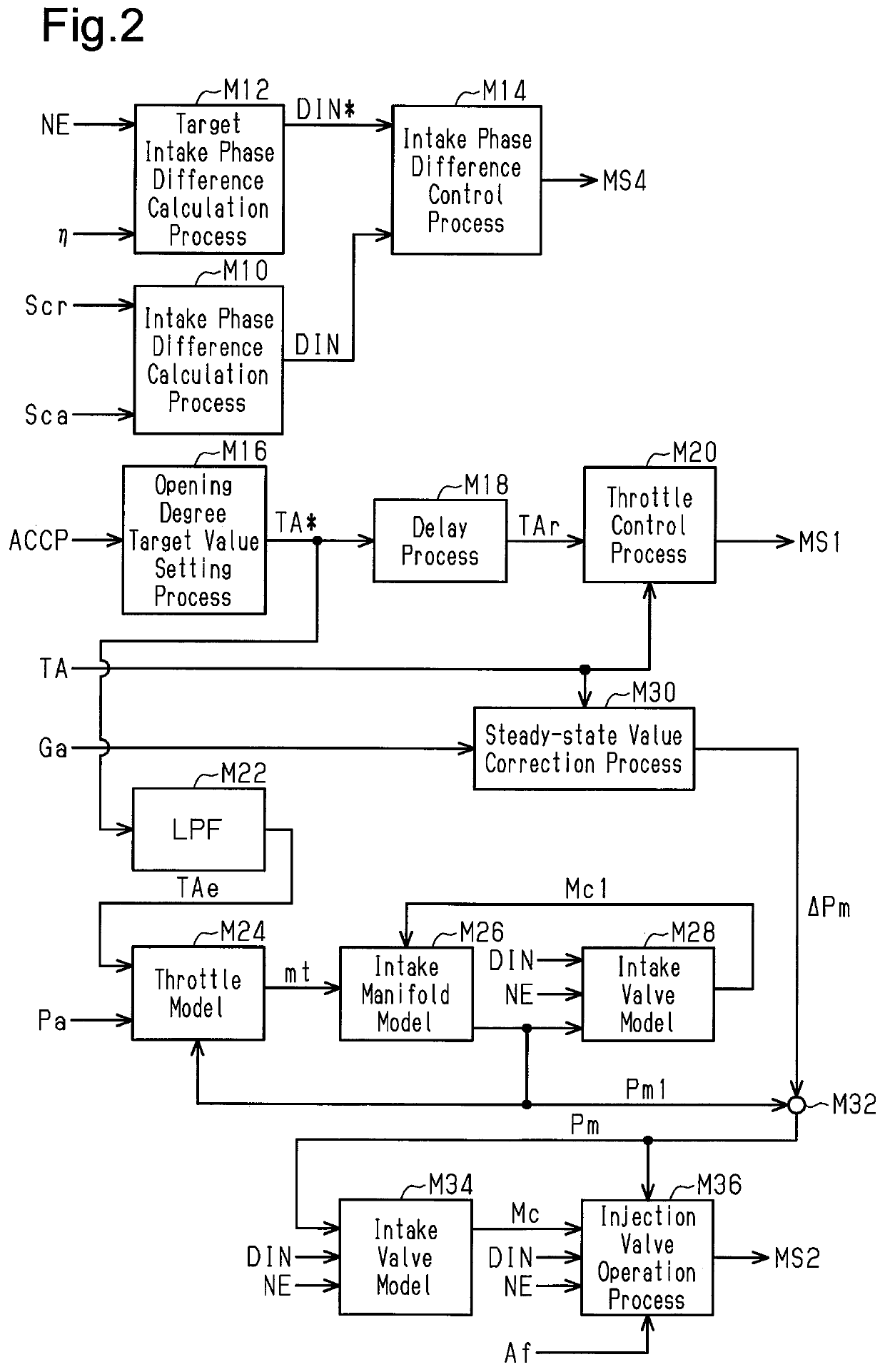
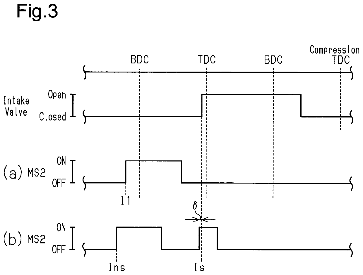
[0041]A controller 50 for an internal combustion engine 10 according to a first embodiment of the present disclosure will now be described with reference to the drawings.
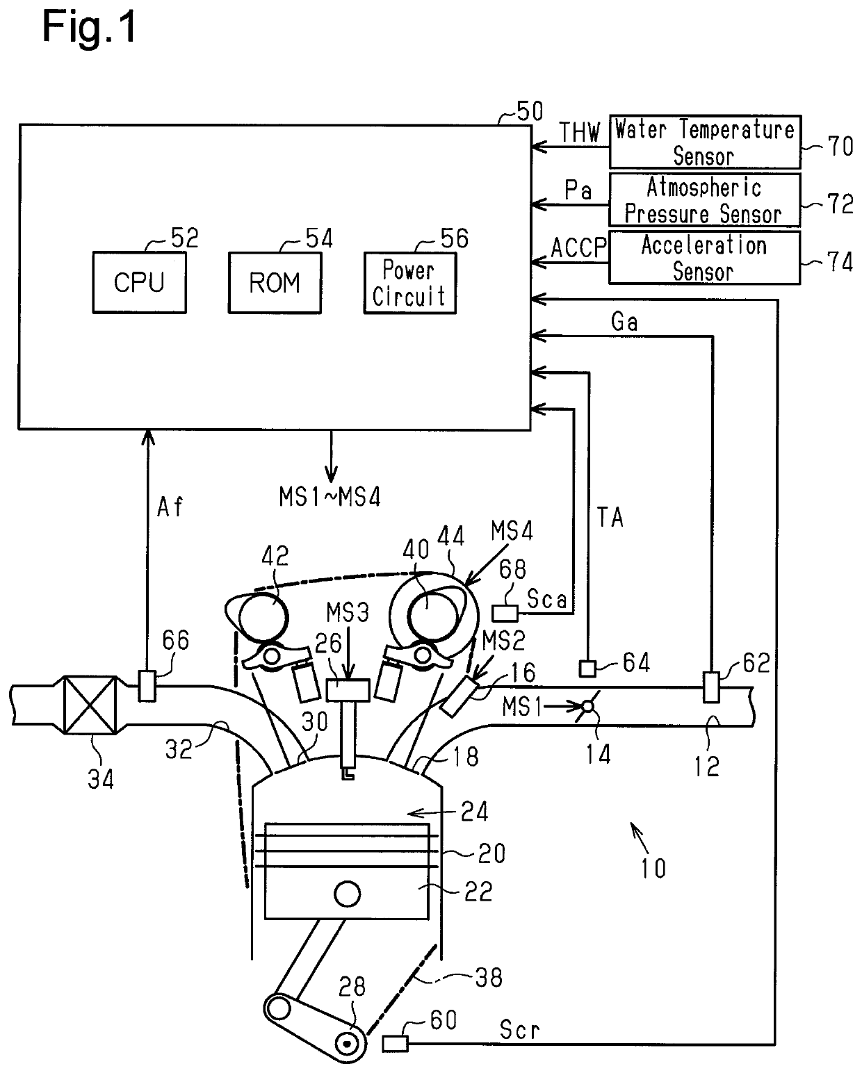
[0042]The internal combustion engine 10 shown in FIG. 1 includes an intake passage 12. The intake passage 12 includes a throttle valve 14. A port injection valve 16 is arranged on the downstream side of the throttle valve 14. When an intake valve 18 opens, air drawn into the intake passage 12 and fuel injected from the port injection valve 16 flow into a combustion chamber 24, which is defined by a cylinder 20 and a piston 22. In the combustion chamber 24, the mixture of the fuel and the air is burned through spark discharge performed by an ignition device 26. Energy generated through the burning is converted by the piston 22 into rotation energy of a crankshaft 28. When an exhaust valve 30 opens, the burned mixture is discharged to an exhaust passage 32 as exhaust gas. The exhaust passage 32 includes a catalyst 34....
second embodiment
[0088]A second embodiment will now be described with reference to FIGS. 9 and 10, focusing on the difference from the first embodiment.
[0089]The processes illustrated in FIG. 9 are implemented when the CPU 52 repeatedly executes the program stored in the ROM 54, for example, in a predetermined cycle. In FIG. 9, the same step numbers are given to the processes corresponding to the processes illustrated in FIG. 4 for illustrative purposes.
[0090]In a series of processes shown in FIG. 9, when the CPU 52 makes an affirmative determination in the process of S36, the CPU 52 determines whether the interval ensuring timing Insi is greater than the last non-synchronous injection start timing Ins(n−1) (S40). When the CPU 52 determines that the interval ensuring timing Insi is greater than the last non-synchronous injection start timing Ins(n−1) (S40: YES), the CPU 52 substitutes the interval ensuring timing Insi into the non-synchronous injection start timing Ins (S42) and then proceeds to the...
third embodiment
[0093]A third embodiment will now be described with reference to FIG. 11, focusing on the difference from the first embodiment.
[0094]The processes illustrated in FIG. 11 are implemented when the CPU 52 repeatedly executes the program stored in the ROM 54, for example, in a predetermined cycle. In FIG. 11, the same step numbers are given to the processes corresponding to the processes illustrated in FIG. 9 for illustrative purposes.
[0095]In a series of processes shown in FIG. 11, when the CPU 52 completes the process of S26, the CPU 52 calculates the reference start timing Insr based on the rotation speed NE and the water temperature THW (S44) and then proceeds to the step of S28. The CPU 52 calculates the value of the reference start timing Insr to be more advanced when the rotation speed NE is high than when the rotation speed NE is low. This is because rotation by the same rotation angle requires a shorter time when the rotation speed NE is high than when the rotation speed NE is ...
PUM
 Abstract
Description
Claims
Application Information
 - R&D
- Intellectual Property
- Life Sciences
- Materials
- Tech Scout
- Unparalleled Data Quality
- Higher Quality Content
- 60% Fewer Hallucinations
Browse by: Latest US Patents, China's latest patents, Technical Efficacy Thesaurus, Application Domain, Technology Topic, Popular Technical Reports.
© 2025 PatSnap. All rights reserved.Legal|Privacy policy|Modern Slavery Act Transparency Statement|Sitemap|About US| Contact US: help@patsnap.com


