Optical imaging system, imaging apparatus and electronic device

a technology of optical imaging and imaging apparatus, applied in the field of optical imaging system and imaging apparatus, can solve the problems of affecting the miniaturization of the image, and affecting the miniaturization

Active Publication Date: 2019-08-13
LARGAN PRECISION
View PDF20 Cites 4 Cited by
  • Summary
  • Abstract
  • Description
  • Claims
  • Application Information

AI Technical Summary

Benefits of technology

[0068]The optical imaging system may further include at least one reflective component such as prism or mirror to make the spatial arrangement more flexible. The at least one reflective component can be disposed at an object side of the first lens element so as to favorably reduce the height of the optical imaging system. The number of the at least one reflective component may be more than 2 according to the requirements of design and the configuration of the reflective surface can be adjusted according to the requirement such as the spatial arrangement. Also, the height, the length and the width of the prism and mirror can be made unequal to reduce the volume occupied. Materials such as glass or plastic can be selected as the material of the prism according to the design. When the at least one reflective component is a prism, the axial distance between the object-side surface of the first lens element and the image-side surface of the fifth lens element is TD, a total length of internal optical paths of the prism is TP, and the following condition can be satisfied: 0.20<TD / TP<1.35, the volume of the system can be maintained.
[0062]When a composite focal length of the first lens element and the second lens element is f12, a composite focal length of the third lens element, the fourth lens element and the fifth lens element is f345, and the following condition can be satisfied: −5.5<f12 / f345<0, the outer diameter in the backend of the system can be favorably reduced by appropriately configuring the refractive power in the frontend and the backend of the system. Preferably, the following condition can be satisfied: −2.5<f12 / f345<−0.58.
[0063]When the focal length of the optical imaging system is f, a curvature radius of the image-side surface of the fifth lens element is R10, and the following condition can satisfied: 4.0<f / R10<10, the incident angle of light on the image surface can be reduced and the occurrence of astigmatism can be favorably reduced.

Problems solved by technology

As a result, using one single shooting module is hard to meet the requirements concurrently.
Conventional small angle telephoto lens usually requires a larger electronic image sensor to maintain high imaging quality, thus a lens with larger outer diameter being required, but that contradicts with the requirements of miniaturization.

Method used


Image

  • Optical imaging system, imaging apparatus and electronic device
  • Optical imaging system, imaging apparatus and electronic device
  • Optical imaging system, imaging apparatus and electronic device

Examples


2nd embodiment

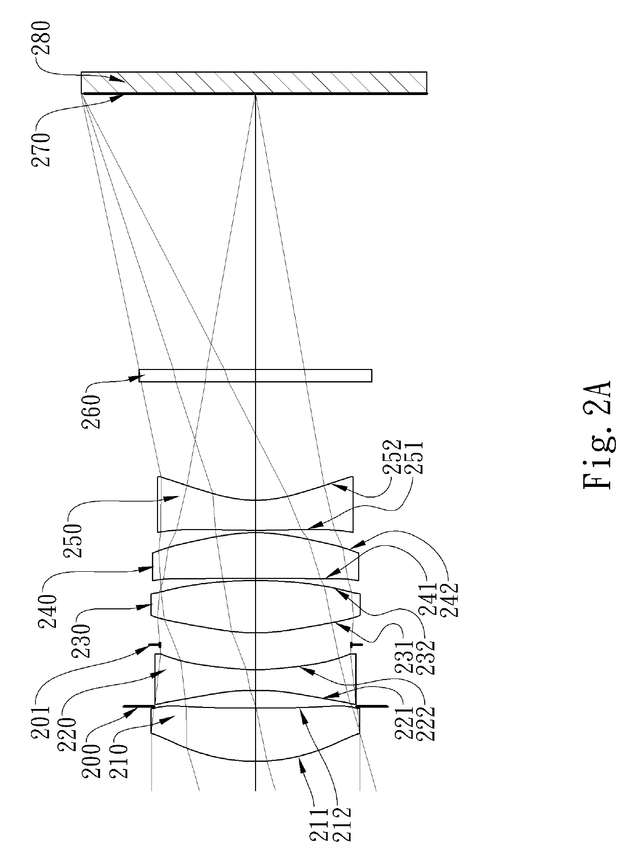
[0117]FIG. 2A is a schematic view of an imaging apparatus according to the 2nd embodiment of the present disclosure. FIG. 2B shows, in order from left to right, longitudinal spherical aberration curves, astigmatic field curves and a distortion curve of the imaging apparatus according to the 2nd embodiment.

[0118]In FIG. 2A, the imaging apparatus includes an optical imaging system (not otherwise herein labeled) of the present disclosure and an image sensor 280. The optical imaging system includes, in order from an object side to an image side, a first lens element 210, an aperture stop 200, a second lens element 220, a stop 201, a third lens element 230, a fourth lens element 240, and a fifth lens element 250. The optical imaging system includes five lens elements (210, 220, 230, 240 and 250) without any other lens elements being inserted between the first lens element 210 and the fifth lens element 250.

[0119]The first lens element 210 with positive refractive power has an object-side...

3rd embodiment

[0131]FIG. 3A is a schematic view of an imaging apparatus according to the 3rd embodiment of the present disclosure. FIG. 3B shows, in order from left to right, longitudinal spherical aberration curves, astigmatic field curves and a distortion curve of the imaging apparatus according to the 3rd embodiment.

[0132]In FIG. 3A, the imaging apparatus includes an optical imaging system (not otherwise herein labeled) of the present disclosure and an image sensor 380. The optical imaging system includes, in order from an object side to an image side, a first lens element 310, an aperture stop 300, a second lens element 320, a stop 301, a third lens element 330, a fourth lens element 340, and a fifth lens element 350. The optical imaging system includes five lens elements (310, 320, 330, 340 and 350) without any other lens elements being inserted between the first lens element 310 and the fifth lens element 350.

[0133]The first lens element 310 with positive refractive power has an object-side...

4th embodiment

[0150]FIG. 4A is a schematic view of an imaging apparatus according to the 4th embodiment of the present disclosure. FIG. 4B shows, in order from left to right, longitudinal spherical aberration curves, astigmatic field curves and a distortion curve of the imaging apparatus according to the 4th embodiment.

[0151]In FIG. 4A, the imaging apparatus includes an optical imaging system (not otherwise herein labeled) of the present disclosure and an image sensor 480. The optical imaging system includes, in order from an object side to an image side, a first lens element 410, an aperture stop 400, a second lens element 420, a third lens element 430, a fourth lens element 440, and a fifth lens element 450. The optical imaging system includes five lens elements (410, 420, 430, 440 and 450) without any other lens elements being inserted between the first lens element 410 and the fifth lens element 450.

[0152]The first lens element 410 with positive refractive power has an object-side surface 411...


PUM


Abstract

An optical imaging system includes five lens elements, the five lens elements being, in order from an object side to an image side: a first lens element having positive refractive power; a second lens element having negative refractive power; a third lens element having positive refractive power; a fourth lens element having positive refractive power; and a fifth lens element having negative refractive power.

Description

RELATED APPLICATIONS[0001]This application claims priority to Taiwan Application Serial Number 106104071, filed on Feb. 8, 2017, which is incorporated by reference herein in its entirety.BACKGROUNDTechnical Field[0002]The present disclosure relates to an optical imaging system and an imaging apparatus, and more particularly, to an optical imaging system and an imaging apparatus applicable to electronic devices.Description of Related Art[0003]With the rapid developments in technology, various electronic devices equipped with multifunction have become a trend in development. At the mean time, requirements of shooting quality become even higher for wider application ranges, such as electronic devices equipped with both macro shooting and telephoto functions. As a result, using one single shooting module is hard to meet the requirements concurrently. Therefore, electronic devices such as smart phones using shooting modules with dual lens or multiple lenses become the mainstream of devel...

Claims


Application Information

Patent Timeline
Patent Type & Authority Patents(United States)
IPC IPC(8): G02B15/14G02B13/02G02B13/00G02B13/14G02B13/18G02B9/60
CPCG02B13/0045G02B13/02G02B13/146G02B13/18G02B9/60
Inventor WU, CHIEN-HSUNKUO, TZU-CHIEHCHEN, KUAN-MING
Owner LARGAN PRECISION
Why Eureka
Try Eureka