
Device and method for indoor mobile mapping of an environment

a mobile mapping and environment technology, applied in the field of mobile or portable indoor mapping system, can solve problems such as measurement errors

Active Publication Date: 2019-08-13
FARO TECH INC
View PDF46 Cites 4 Cited by
  • Summary
  • Abstract
  • Description
  • Claims
  • Application Information

AI Technical Summary

Benefits of technology

The invention provides a method and system for scanning and measuring an environment using a 3D measurement device and a mobile platform. The device can determine the distance to a surface in the area based on the speed of light, using a helical or compound mode. The mobile platform moves from a first position, and the device collects a first set of 3D coordinates of the area. Then, a second set of 3D coordinates is collected using a second device that projects a light pattern and captures an image of it. The second device can determine the 3D coordinates of at least one point on a surface in the area with six-degrees of freedom. The first set of 3D coordinates is registered based on the second set of 3D coordinates. This technology allows for more accurate and precise scanning of environments and the ability to measure in 6D.

Problems solved by technology

While the inertial measurement units will track the location of the system, these systems tend to drift as the mobile system is moved resulting in errors in the measurements.

Method used


Image

  • Device and method for indoor mobile mapping of an environment
  • Device and method for indoor mobile mapping of an environment
  • Device and method for indoor mobile mapping of an environment

Examples


Embodiment Construction

[0021]In one embodiment, a portable or mobile indoor mapping system is provided that generates three-dimensional coordinates of points on surfaces of an indoor area. In an embodiment, advantages are provided in the measuring of the position and orientation of the system with six-degrees of freedom as the mobile indoor mapping system is moved from a first position to a second position. In an embodiment, advantages are provided in using the position and orientation of the mobile indoor mapping system to register three-dimensional coordinate data of the indoor area.

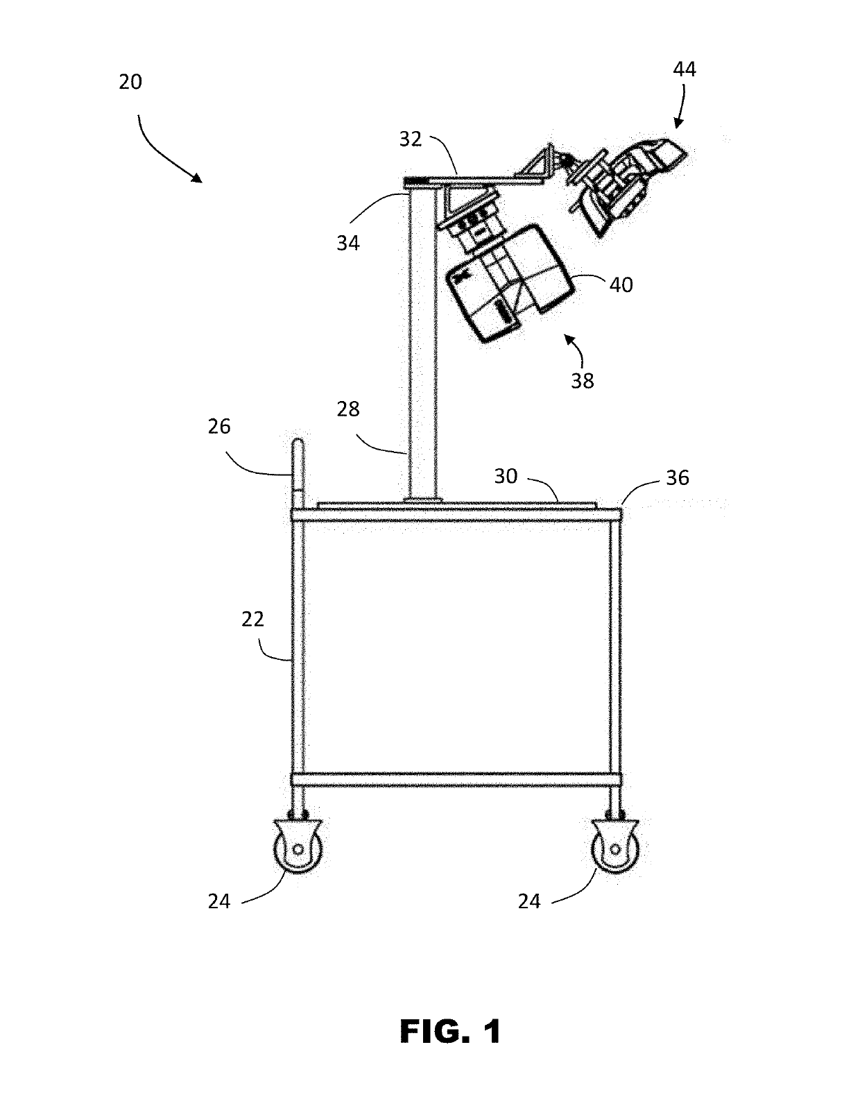
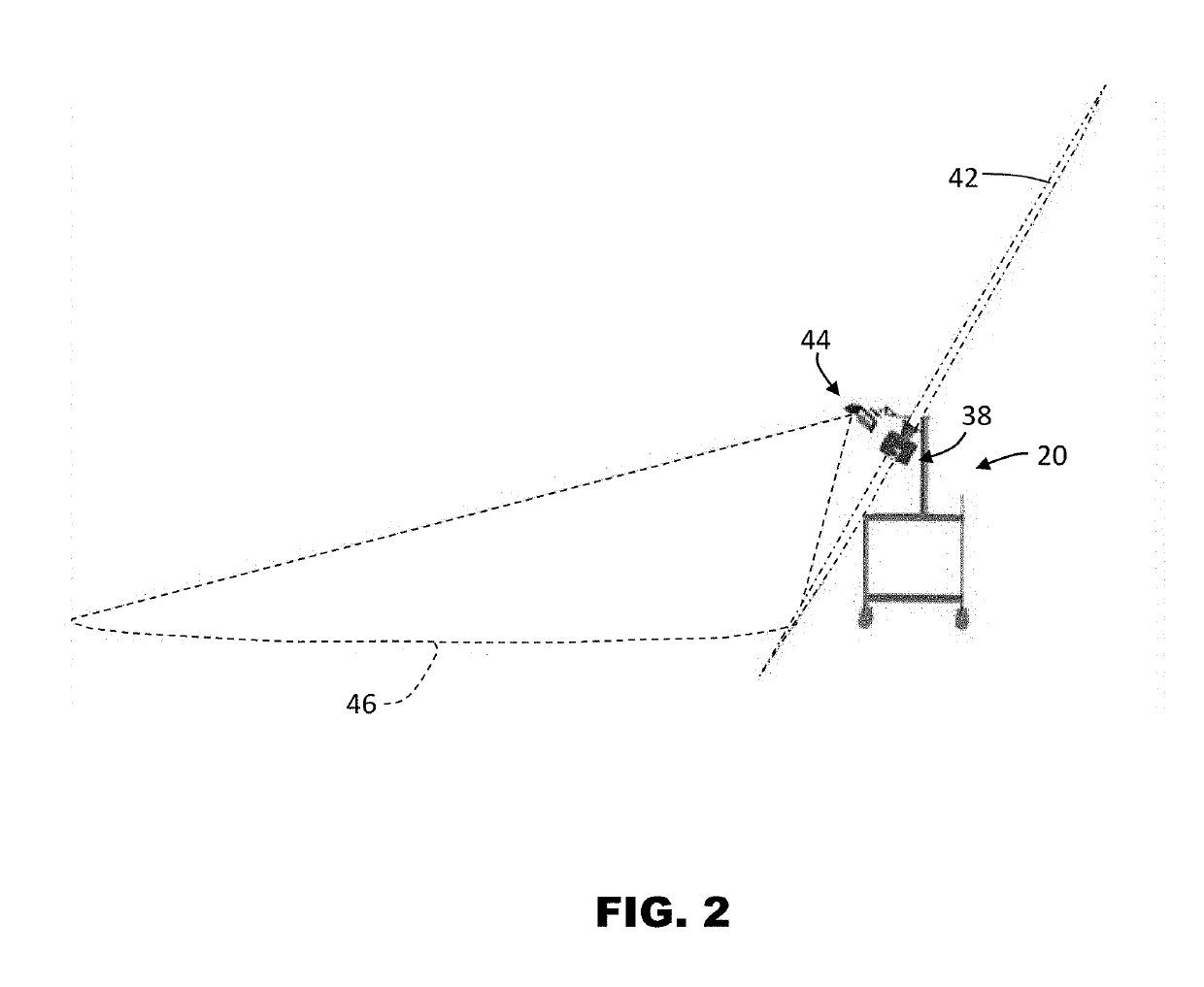
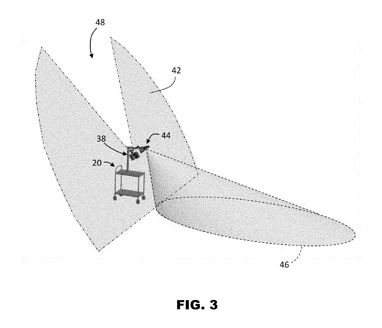
[0022]Referring now to FIG. 1, an embodiment is shown of an indoor mapping system 20. In the exemplary embodiment, the system 20 includes a mobile platform 22 that allows the system 20 to be moved about the indoor area where mapping is desired. The mobile platform 22 may include wheels 24 that allow the mobile platform to be rolled over the floor in the area being scanned, such as by an operator (not shown) pushing on a hand...


PUM


Abstract

A method and system for scanning and measuring an environment is provided. The method includes providing a first three-dimensional (3D) measurement device. The 3D measurement device being operable in a helical mode or a compound mode, wherein a plurality of light beams are emitted along a first path defined by a first axis and a second axis in the compound mode and along a second path defined by the first axis in the helical mode. A mobile platform holding the 3D measurement device is moved from a first position. A first group of 3D coordinates of the area is acquired by the 3D measurement device when the mobile platform is moving. A second group of 3D coordinates of the area is acquired with a second 3D measurement device that with six-degrees of freedom (6DOF). The first group of 3D coordinates is registered based on the third group of 3D coordinates.

Description

CROSS REFERENCE TO RELATED APPLICATION[0001]This application claims the benefit of U.S. Provisional Application Ser. No. 62 / 399,613, filed Sep. 26, 2016, the entire disclosure of which is incorporated herein by reference.BACKGROUND[0002]The subject matter disclosed herein relates to a mobile or portable indoor mapping system, and in particular, to a system that can quickly and accurately generate three-dimensional coordinates of an indoor area.[0003]The creation of three-dimensional (3D) computer models of existing structures has a number of uses in architecture, construction, archeology, and reconstruction applications. One method of generating the 3D computer model is using a laser scanner device. A laser scanner emits a beam of light and determines the 3D coordinates to a surface that reflects the light. The determination of the distance may be based on the time-of-flight of the light beam. Some laser scanner devices use a rotating mirror to reflect the light into the environment...

Claims


Application Information

Patent Timeline
Patent Type & Authority Patents(United States)
IPC IPC(8): G06T7/33G06T7/73H04N13/25G06T7/55G06T7/579G01S17/87G01S17/89G01S17/02G01S17/42G01S17/48G01S7/481G01S7/497G06T7/70G06T7/521G01S5/16H04N13/254G01S17/86
CPCG06T7/344G01S7/4812G01S7/4813G01S7/4817G01S7/497G01S17/023G01S17/42G01S17/48G01S17/87G01S17/89G06T7/521G06T7/55G06T7/579G06T7/70G06T7/73H04N13/25G01S5/16H04N13/254G06T2207/10016G06T2207/10024G06T2207/10028G06T2207/10048G06T2207/10152G06T2207/30244G01S17/86
Inventor WOHLFELD, DENIS
Owner FARO TECH INC
Learn More