Power limiting circuit for an inverter device, and inverter device

a technology of inverter circuit and power limit circuit, which is applied in the direction of power conversion system, ac-dc conversion, electrical apparatus, etc., can solve the problems of large weight of power supply devices, inconvenient movement and carrying around, and inability to meet the needs of electric power, so as to reduce the input reduce the output power of inverter circuits , the effect of small equivalent resistan

Inactive Publication Date: 2019-08-13
SHANGHAI SUNSON ACTIVATED CARBON TECH
View PDF10 Cites 0 Cited by
  • Summary
  • Abstract
  • Description
  • Claims
  • Application Information

AI Technical Summary

Benefits of technology

[0023]the adder is connected to a drive circuit for the DC-DC converter circuit of the inverter device, for lowering the output voltage of the DC-DC converter circuit when the input power of the inverter device exceeds the preset power threshold.
[0026]The technical scheme of the present invention has the following advantages:
[0027](1) In the power limiting circuit for an inverter device provided by the embodiments of the present invention, there is provided a shunt resistance R125 which is connected in parallel to the input ends of inverter circuit after the shunt resistance R125 is connected in series with a MOSFET tube used as a first controllable switch Q15, the gate electrode of this MOSFET tube is used as a control end that is connected to the output end of the first logic judging circuit. When the input current (DC circuit current) of the inverter circuit exceeds a first preset current threshold, the MOSFET tube closes to connect the shunt resistance R125 in parallel to the DC input circuit of the inverter circuit, thereby shunting a part of the current and thus reduces the input power of the inverter circuit.
[0028](2) The power limiting circuit for an inverter device provided by the embodiments of the present invention further comprises a current-limiting circuit that comprises a first current-limiting resistance, a second current-limiting resistance and a second controllable switch, wherein, the first current-limiting resistance is connected in series in a DC input circuit of the inverter circuit, a first end of the second current-limiting resistance is connected to a first end of the second controllable switch, a second end of the second current-limiting resistance and a second end of the second controllable switch are respectively connected to two ends of the first current-limiting resistance, a control end of the second controllable switch is connected to an output end of the first logic judging circuit for controlling the second controllable switch to disconnect when the input current of the inverter circuit exceeds the first preset current threshold. Because a parallel-connected resistance has a smaller equivalent resistance, it has a smaller voltage-dividing capability and has a smaller current-limiting capability under a certain voltage. When the input current of the inverter circuit is at normal state, i.e. being lower than the first preset current threshold, the parallel-connected first and second current-limiting resistances are both being connected. When the DC input current (input current) of the inverter circuit exceeds a first preset current threshold, the second controllable switch disconnects to cut off the second current-limiting resistance, so that the voltage drop on the first current-limiting resistance increases, and the input current of the inverter circuit decreases correspondingly when the input voltage of the inverter circuit keeps constant or becomes lower. This current-limiting circuit further reduces the input current of the inverter circuit, in addition to the effect of the shunt circuit, and thereby further reduces the power of the inverter circuit.
[0030](4) The power limiting circuit for an inverter device provided by the embodiments of the present invention does not need to accurately acquire the input power of the inverter device, and only needs to judge whether the input power exceeds a preset power threshold, therefore, under the circumstance that the input voltage of the inverter device does not fluctuate much, the input power of the inverter device can be estimated by sampling the input current and input voltage of the inverter device and then processing them with an adder. This method has a simple circuit arrangement and high reliability.
[0031](5) The inverter device provided by the embodiments of the present invention can be directly loaded with an inductive load having a starting current far larger than its rated current. When the inductive load is started, as the output current of the inverter device increases, the current on the input ends of the inverter device increases correspondingly, and if the current on the input ends of the inverter device exceeds the first preset current threshold, it is then judged that the circuit has over-current, i.e. exceeding a maximum working power of the inverter device, and at this time, by shunting and current-limiting, the working power of the inverter device can be reduced. The power limiting circuit for inverter device makes it possible for the inverter device to be directly loaded with an inductive load, while an industrial frequency transformer can be dispensed with, so that the weight of the inverter device is greatly reduced to be easy to move and carry around. Furthermore, the inverter device provided with this power limiting circuit does not need to set a very large maximum working power, instead the maximum working power only needs to be slightly larger than the rated working power of the inductive load, so that the equipment cost is greatly reduced.

Problems solved by technology

Therefore, the technical problem to be solved by the present invention is that, when direct current power stored in an energy-storing battery is converted into alternate current power to supply power to a load, the electric power is not suitable to be supplied to an inductive load, and if an industrial frequency transformer is used to solve the problem of how to load the circuit with an inductive load, the transformer would cause the power supply device to have a large weight and be inconvenient to move and carry around.

Method used


Image

  • Power limiting circuit for an inverter device, and inverter device
  • Power limiting circuit for an inverter device, and inverter device
  • Power limiting circuit for an inverter device, and inverter device

Examples


embodiment 1

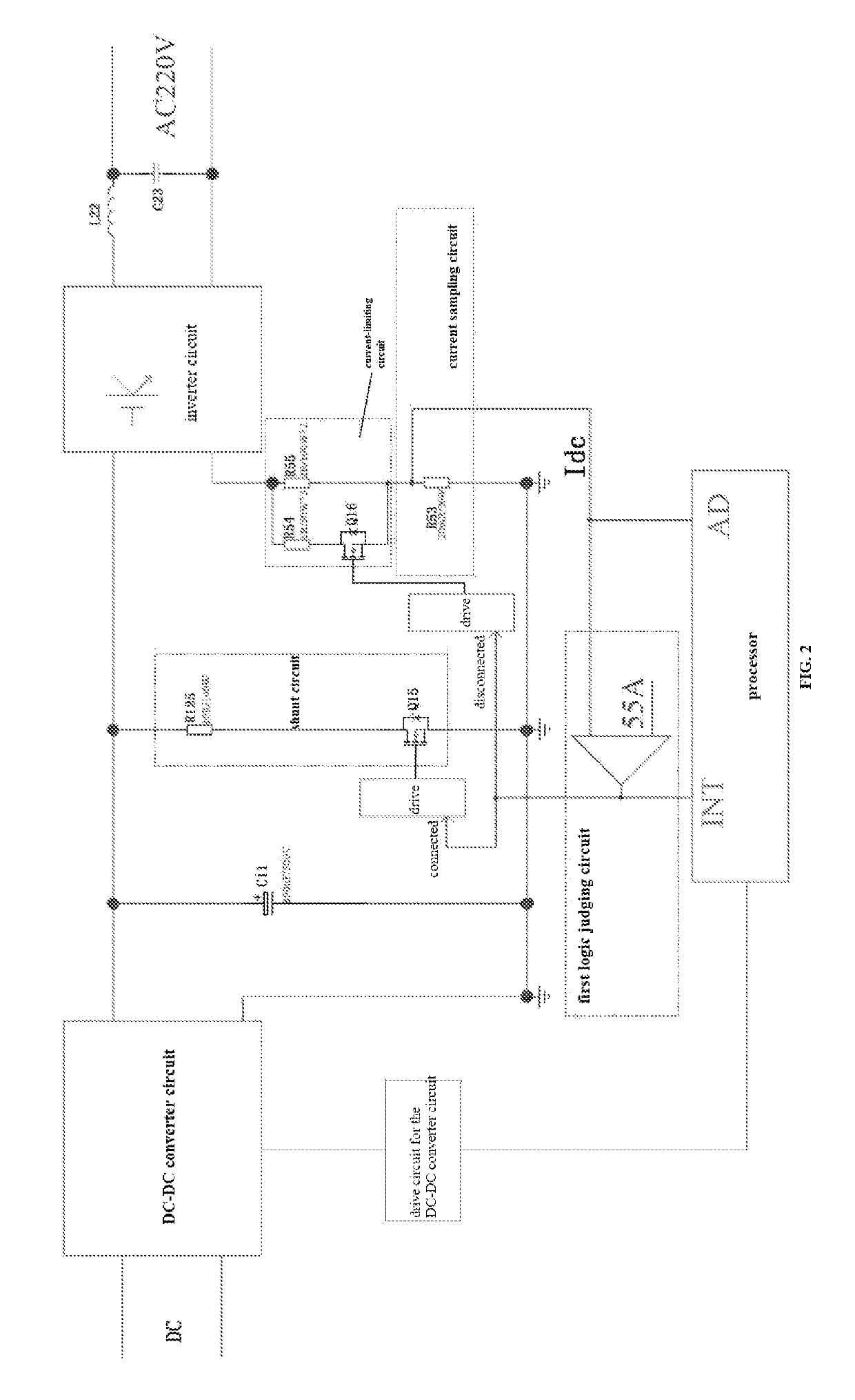
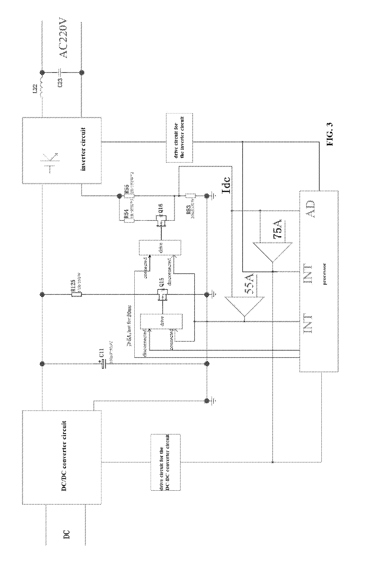
[0042]As shown in FIG. 2 to FIG. 5, this embodiment provides a power limiting circuit for an inverter device that comprises:

[0043]a first logic judging circuit for comparing an input current of an inverter circuit of the inverter device with a first preset current threshold and outputting a first signal when said input current is larger than the first preset current threshold; and

[0044]a shunt circuit for shunting a portion of the input current of the inverter circuit when receiving said first signal; wherein, the shunt circuit comprises a shunt resistance R125 and a first controllable switch Q15, a first end of the shunt resistance R125 is connected to a first end of the first controllable switch Q15, a second end of the shunt resistance R125 is connected to one input end of the inverter circuit, a second end of the first controllable switch Q15 is connected to the other input end of the inverter circuit, a control end of the first controllable switch Q15 is connected to an output ...

embodiment 2

[0057]As shown in FIG. 6, this embodiment provides a power limiting circuit for an inverter device, and as compared to Embodiment 1 above, its difference lies in that: it also comprises an input power limiting circuit that comprises an input current sampling circuit, an input voltage sampling circuit and an adder.

[0058]The input current sampling circuit is for sampling the input current of a DC-DC converter circuit of the inverter device and transforming the sampled current signal into corresponding voltage signal. In particular, the current on an input circuit of the DC-DC converter circuit is sampled.

[0059]The input voltage sampling circuit is for sampling the input voltage of the DC-DC converter circuit of the inverter device. In particular, the voltage is sampled by means of a first voltage-dividing resistance R22 and a second voltage-dividing resistance R29.

[0060]The adder is for adding the voltage signal outputted by the input current sampling circuit and the voltage signal ou...

embodiment 3

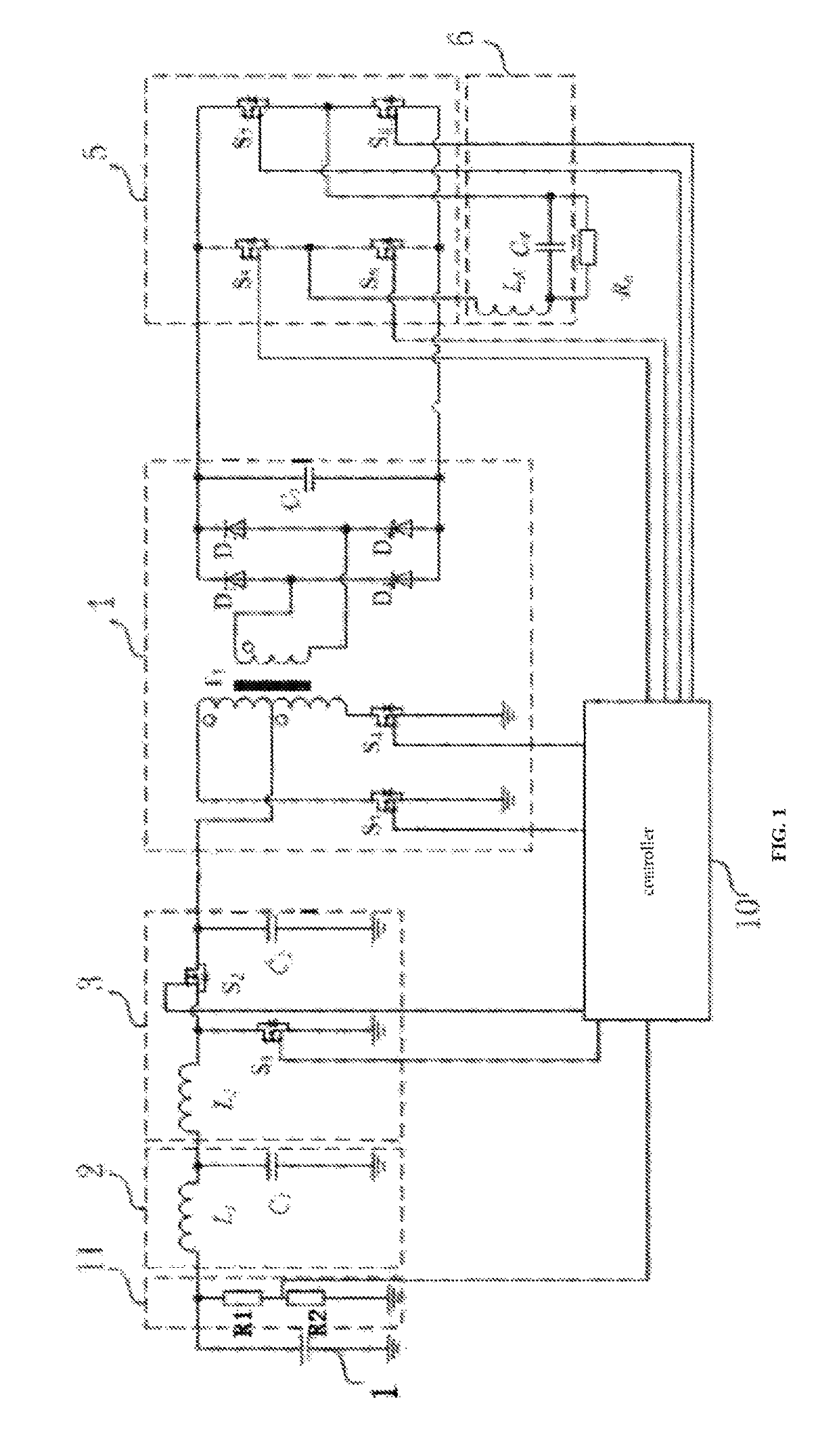
[0067]This embodiment provides an inverter device that comprises a DC-DC converter circuit and an inverter circuit connected in series; a drive circuit for the DC-DC converter circuit; a drive circuit for the inverter circuit; and a processor for controlling the drive circuit for the DC-DC converter circuit and the drive circuit for the inverter circuit; it also comprises a power limiting circuit for an inverter device as described in Embodiment 1 or 2 above.

[0068]Also, a capacitor C11 is connected in parallel to output ends of the DC-DC converter circuit. This capacitor C11 has wave-filtering function as well as energy-storing function. When the inverter circuit needs to be loaded with a load having a large starting current, this capacitor C11 with energy-storing function is indispensable. In practical implementation, multiple capacitors (which may be an electrolytic capacitor) connected in parallel may be arranged to carry out the wave-filtering and energy-storing functions.

[0069]...


PUM


Abstract

The present invention provides a power limiting circuit for inverter device and an inverter device, which pertains to the technical field of power source inverting. The inverter device comprises a first logic judging circuit for comparing an input current of an inverter circuit with a first preset current threshold and outputting a first signal when said input current is larger than the first preset current threshold; and a shunt circuit for shunting a portion of the input current of the inverter circuit when receiving said first signal; wherein, the shunt circuit comprises a shunt resistance and a first controllable switch, the shunt resistance and the first controllable switch are connected in series and then parallel-connected to input ends of the inverter circuit, a control end of the first controllable switch is connected to an output end of the first logic judging circuit for controlling the first controllable switch to be connected when receiving said first signal. This circuit enables the inverter device to be directly loaded with an inductive load, while an industrial frequency transformer can be dispensed with, so that the weight of the inverter device is greatly reduced, which allows the inverter device to be easy to move and carry around.

Description

TECHNICAL FIELD[0001]The present invention pertains to the technical field of power source inverting, and in particular relates to a power limiting circuit for inverter device and an inverter device.BACKGROUND[0002]An inverter circuit is used to convert the electric power (direct current) stored in an electric power storing device into alternate current so as to supply alternate current power to loads. The utility model patent with a publication number of CN203951381U discloses an on-board inverter system, as shown in FIG. 1, which comprises a direct current power source 1, a filter circuit 2, a Boost circuit 3, a DC-DC Boost circuit 4, a DC-AC inverter circuit 5, an alternate current filter circuit 6, a voltage measuring circuit 11 and a controller 10 for controlling the Boost circuit 3, the DC-DC Boost circuit 4 and the DC-AC inverter circuit 5.[0003]Because an inductive load (such as a motor) has very large starting current (normally 4-7 times of the rated current), it also has v...

Claims


Application Information

Patent Timeline
Patent Type & Authority Patents(United States)
IPC IPC(8): H02M1/32H02M1/36H02M1/34H02M7/5387H02M1/00
CPCH02M1/32H02M1/36H02M7/53871H02M2001/344H02M2001/007H02M2001/325H02M1/34H02M7/5387H02M1/007H02M1/325H02M1/344
Inventor XIE, JUN
Owner SHANGHAI SUNSON ACTIVATED CARBON TECH
Why Eureka
Try Eureka