Spray gun filter for filtering liquid

a technology of spray gun and liquid filter, which is applied in the direction of cartridge filter, filter element filter, combustion process, etc., can solve the problem of dead spa

Active Publication Date: 2019-08-20
J WAGNER GMBH
View PDF8 Cites 0 Cited by
  • Summary
  • Abstract
  • Description
  • Claims
  • Application Information

AI Technical Summary

Benefits of technology

[0003]An object of the invention is to specify a spray gun filter for filtering liquid, said spray gun filter having a longer service life and at the same time smaller dimensions.
[0004]Advantageously, there is no need for an additional component, such as the spring in the embodiment according to FIG. 2, in order to fix the spray gun filter in the filter housing. The production costs can thus be reduced. Since the additional component is omitted, it can also no longer become lost and also does not have to be cleaned. The maintenance effort for the personnel is reduced and the risk of the spring and the spray gun filter being inserted incorrectly into the filter housing is likewise reduced.
[0005]A further advantage of the spray gun filter according to the invention lies in the fact that no filter residues and impurities remain in the filter housing of the spray gun once the spray gun filter has been removed from the filter housing. In addition, the spray gun filter according to the invention generates a lower pressure loss.

Problems solved by technology

In addition, the spray gun filter 100 has the disadvantage that a spring 111 is necessary in order to fix the spray gun filter 100 in the correct position in the filter housing 112, 116.
A further disadvantage of the spray gun filter 100 is that it has a dead space 106 at the upstream end, said dead space increasing the overall length of the spray gun filter 100 and therefore also of the filter housing 112, 116.

Method used


Image

  • Spray gun filter for filtering liquid
  • Spray gun filter for filtering liquid
  • Spray gun filter for filtering liquid

Examples


first embodiment

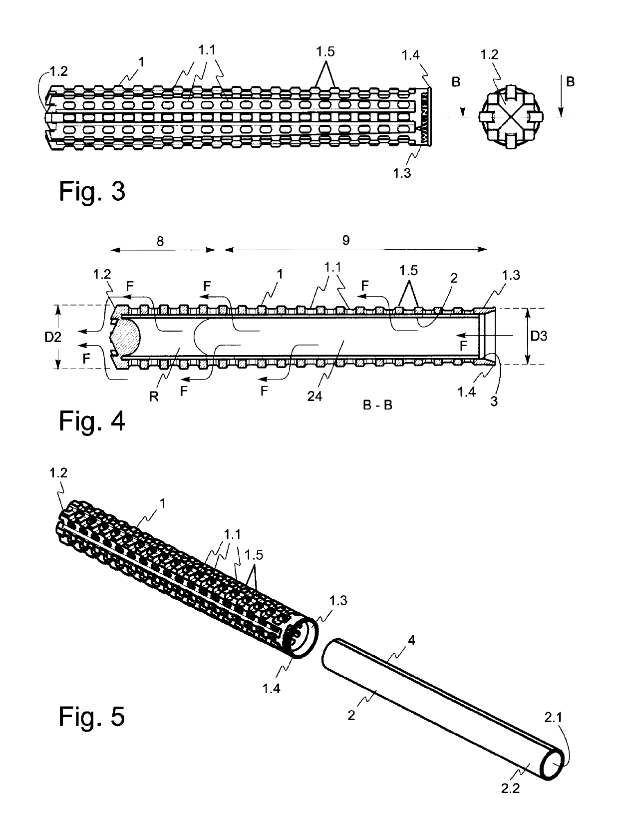
[0049]FIG. 3 shows a first possible embodiment of the spray gun filter according to the invention in a side view and in a front view, that is to say as viewed from the filter head 1.2. The first embodiment of the spray gun filter according to the invention is illustrated in longitudinal section in FIG. 4. Lastly, FIG. 5 shows the first embodiment of the spray gun filter according to the invention in an exploded view. The spray gun filter comprises a tubular filter support 1 and a cylindrical filter fabric 2 arranged within the filter support 1. The outer face 2.2 of the filter fabric 2 bears against the inner face of the filter support 1.

[0050]The filter support 1 comprises an inlet 1.3, through which liquid F to be filtered flows into the interior 24 of the spray gun filter. From here, the liquid F is pressed outwardly through the filter fabric 2, wherein particles, impurities and clumps are retained inside the spray gun filter. The retained material R is illustrated symbolically i...

second embodiment

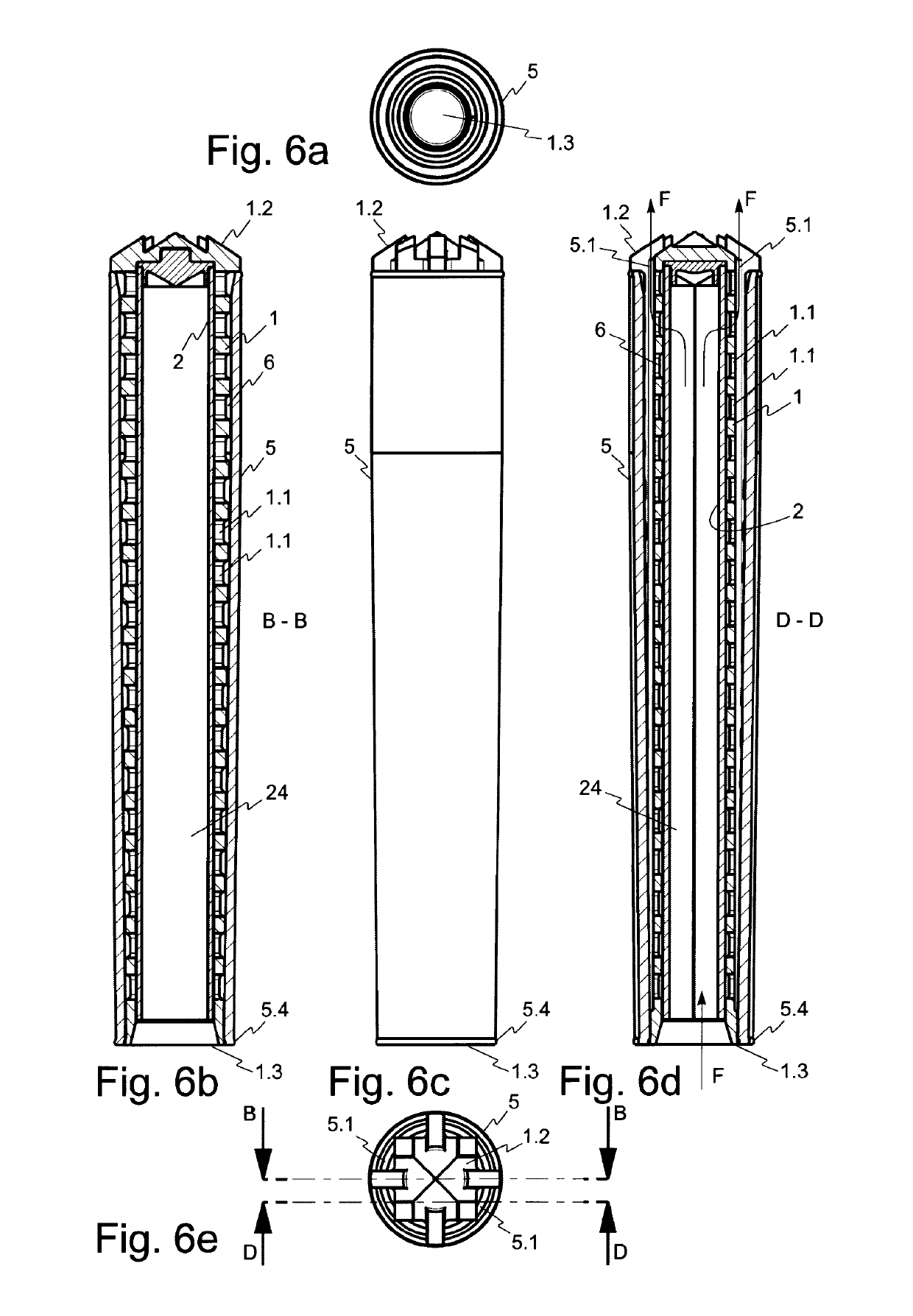
[0055]A second possible embodiment of the spray gun filter according to the invention is illustrated in FIGS. 6a, 6b and 6c as viewed from the inlet side, in longitudinal section taken along the line of section B-B, and in a side view. FIGS. 6d and 6e show the second embodiment of the spray gun filter in longitudinal section taken along the line of section D-D and as viewed from the front.

[0056]The second embodiment basically differs from the first embodiment in that an additional sleeve 5 is provided, in which the filter support 1 is fitted together with the filter fabric. The outer face of the filter support 1 and the inner face of the sleeve 5 together form a channel 6 for the filtered liquid F. The outlet openings 5.1 in the spray gun filter are located at the filter head 1.2.

[0057]Since the filtered liquid F is guided through the channel 6 and only exits from the spray gun filter at the filter head 1.2 through the outlet openings 5.1, it does not come into contact with the filt...

third embodiment

[0058]FIGS. 7a, 7b and 7c show a third possible embodiment of the spray gun filter according to the invention in longitudinal section taken along the line of section B-B in a side view and as viewed from the inlet side.

[0059]The third embodiment basically differs from the second embodiment in that a sleeve 22 is provided, in which the filter fabric 2 is fitted. The sleeve 22 is used as a filter support for the filter fabric 2 and, together therewith, forms a channel 6, through which the filtered liquid F is transported away. The outlet openings 22.6 are located at the filter head 22.2 in the third embodiment.

[0060]Similarly to the third embodiment, the filtered liquid F does not come into contact with the filter housing 12, 16 of the spray gun 10. If the liquid F hardens in the spray gun filter, the spray gun filter does not stick to the filter housing 12, 16. The force applied to remove the spray gun filter can thus be reduced yet further compared to the first embodiment.


PUM

PropertyMeasurementUnit
pressureaaaaaaaaaa
pressureaaaaaaaaaa
pressuresaaaaaaaaaa

Abstract

The spray gun filter according to the invention for filtering liquid comprises a filter fabric and a filter support, which has outlet openings for the liquid and which surrounds the filter fabric from the outside.

Description

TECHNICAL FIELD[0001]The invention relates to a spray gun filter, which is arranged on, or in the vicinity of, the spray gun and is suitable for filtering liquid, such as coating material.PRIOR ART[0002]Previously, the spray gun filter 100 shown in FIGS. 1 and 2 was used in spray guns 110. The spray gun filter 100 comprises a tubular filter support 101 and a tubular filter fabric 102, which surrounds the outer lateral surface of the filter support. Coating material F is pressed externally through the filter fabric 102 under pressure, generally between 80 and 500 bar, and then flows along a channel 103, which is located between the filter fabric 102 and the filter support 101. In the filter support 101, outlet openings 104 are provided, which connect the channel 103 to the interior 105 of the filter support 101. The coating material F thus flows through the channel 103 and the outlet openings 104 into the interior 105 of the filter support 101. From here, the filtered coat-ing materi...

Claims


Application Information

Patent Timeline
Patent Type & Authority Patents(United States)
IPC IPC(8): B05B15/40B01D29/05B05B9/04
CPCB05B15/40B01D29/05B05B9/0403B01D2201/0415B01D2201/04B01D2201/0407
Inventor MAZENAUER, ROLF
Owner J WAGNER GMBH
Why Eureka
Try Eureka