Wind turbine blade handling aboard a vessel

a technology for wind turbine blades and vessels, which is applied in the direction of waterborne vessels, engine fuctions, renewable energy products, etc., can solve the problems of wasting already limited space on board the vessel, affecting the operation of the vessel, so as to improve the handling method and improve the transportation configuration. , the effect of increasing safety

Active Publication Date: 2019-08-20
VESTAS WIND SYST AS
View PDF27 Cites 2 Cited by
  • Summary
  • Abstract
  • Description
  • Claims
  • Application Information

AI Technical Summary

Benefits of technology

[0007]An improved method for blade handling aboard a vessel is provided. The method may in particular be carried out aboard an installation vessel. In particular, the method of the invention may comprise providing on a vessel, a blade rack arrangement configured to accommodate more than one blade, the rack arrangement comprising at least a root rack and a tip rack, wherein the root rack and tip rack between them define a blade support plane; and providing a jack acting between the vessel and one of the root or tip rack; and raising or lowering one of the root or tip rack aboard the vessel by means of the jack to thereby move the blade support plane through an elevation angle. The jack may comprise any suitable drive for raising or lowering a heavy bulky load such as a tip or root rack loaded with blades. The jack may preferably be powered. A suitable drive element for a jack may be a hydraulic drive. By raising or lowering a root or tip rack aboard a vessel by means of a jack, to thereby move a blade support plane through an elevation angle, a substantial improvement in the transportation configuration can be achieved using simple means. Increased safety and reduced costs can thereby result, while at the same time preserving the advantages of existing blade loading and unloading arrangements into or out of a blade rack arrangement. The method of the invention may give rise to numerous potential advantages. For example, it ensures that blades may be stowed on board in a different angular orientation than the orientation in which they are loaded or unloaded. It also ensures that a stowage angle of the blades can be selected, according to criteria such as vessel type or expected water, sea or weather conditions. In other words, it can ensure blade stowage optimisation independently of certain blade loading and unloading considerations. The method also enables a maximisation of the use of limited space aboard a vessel, even allowing for transportation of more blades on a given deck space or height. The invention further allows the provision of lower, smaller spacer frame arrangements thereby saving expense.
[0008]In an optional, preferred aspect of the invention, the other one of the root or tip rack is substantially not raised or lowered. Accordingly, the invention may encompass raising or lowering a tip rack while maintaining the root rack substantially unmoved in relation to the loading deck. Conversely, the root rack may be raised or lowered while the tip rack is maintained substantially unmoved in relation to the loading deck. In a further optional aspect, the root or tip rack which is maintained unmoved, may preferably be positioned atop a static base frame, supported at a height above a loading deck of said vessel. Accordingly, one effect of raising a moveable one of a tip or root rack in relation to a static base frame at an opposite, facing rack is to cause the tip of any blade supported in the relevant rack arrangement to be raised to a level higher than the height of the static base frame above the loading deck. More particularly, the clearance height between the water surface outboard said vessel and the tip of a blade in a blade rack arrangement aboard said vessel will be greater or significantly greater than the base frame height above the vessel deck. Moreover, since the blade support plane is thereby inclined, the clearance between a blade and the water surface outboard the vessel progressively increases along the blade length to its tip. Advantageously therefore, the present invention may lend itself to the safe handling and transportation of longer blades. Inclination of the blades makes blade length independent from required spacer frame height.

Problems solved by technology

This creates a hazard in the form of a risk of blade dipping in agitated waters or in case the vessel would encounter swell.
This is very costly in terms of construction material and it wastes already limited space on board the vessel.

Method used


Image

  • Wind turbine blade handling aboard a vessel
  • Wind turbine blade handling aboard a vessel
  • Wind turbine blade handling aboard a vessel

Examples


Embodiment Construction

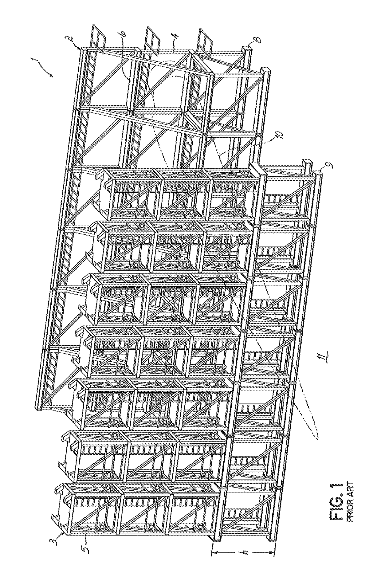
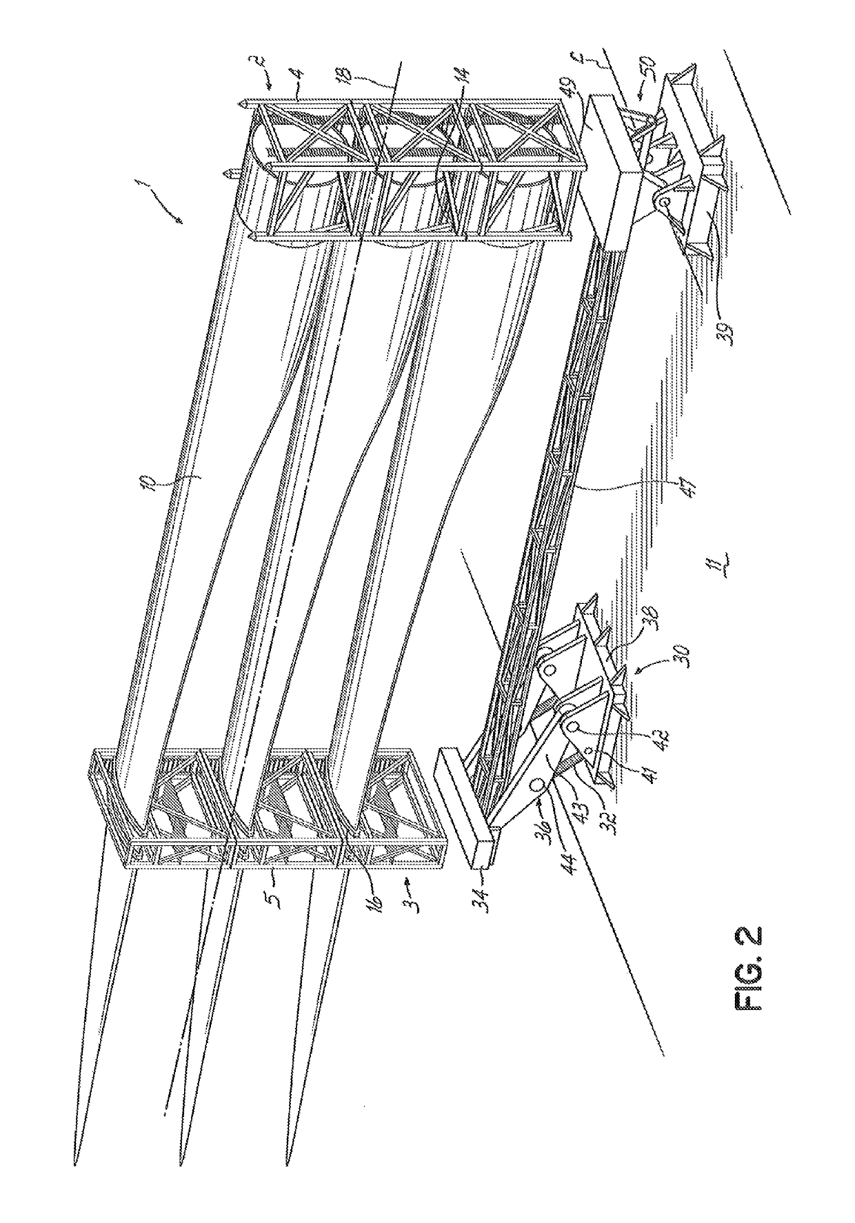
[0029]The term “rack arrangement” is a collective term intended to denote a blade storage construction providing a support structure for wind turbine blades with support elements at or towards the blades' root ends and at or towards their tip ends in the form of a respective, facing root and tip rack. So-called “tip end” support may in particular be provided by means of a tip frame or tip rack at or near a mid-portion of a blade, towards the blade tip. So-called “root end” support may in particular be provided by means of a root frame or root rack at or near a root end of a blade. Preferably, a root end support frame or root rack is provided at the blade root end. A root or tip rack may be unitary or modular although the modular type may be preferred. Each blade may preferably be stored in a frame pair. A root or tip rack may be established by providing one or more frames in a fixed arrangement on a working platform such as on a loading deck of a vessel. The rack arrangement may be ...


PUM


Abstract

A method is provided for handling wind turbine blades aboard a vessel, the method including providing on the vessel a blade rack assembly configured to accommodate more than one blade, the rack assembly having at least a root rack and a tip rack, and the root rack and tip rack defining between them a blade support plane. The method also includes providing a jack acting between the vessel and one of the root or tip rack; and raising or lowering one of the root or tip rack aboard the vessel by the jack to thereby move the blade support plane through an elevation angle θ. A jack assembly on a wind turbine installation vessel and an offshore wind turbine installation vessel are also provided, each capable of raising or lowering a rack of wind turbine blade root or tip support frame elements.

Description

BACKGROUND[0001]The present invention relates to the handling of wind turbine blades aboard a vessel, in particular an installation vessel for wind turbines, especially offshore wind turbines.[0002]Long-distance shipping of wind turbine blades typically involves arranging the blades longitudinally inside the hull or transport compartment of a ship. For the purposes of installing wind turbines, especially offshore wind turbines, the main wind turbine elements such as tower, nacelle and blades or rotors are typically loaded aboard an installation vessel equipped with ancillary equipment for turbine erection. Installation vessels typically resemble a floating work platform more than a traditional transport ship. These vessels are generally loaded with turbine elements at a coastal location local to the planned turbine erection site.[0003]Wind turbine blades may be transported aboard vessels such as installation vessels by placing them in racks on a loading surface such as a deck. The b...

Claims


Application Information

Patent Timeline
Patent Type & Authority Patents(United States)
IPC IPC(8): F03D13/40B63B25/00B63B35/00
CPCF03D13/40B63B25/00B63B35/003F05B2230/6102Y02P70/523F05B2260/02Y02E10/721Y02E10/727F05B2240/95Y02E10/72Y02P70/50B63B25/002B63B25/28
Inventor BOTWRIGHT, ADRIANURSELL-SMITH, MARKMAROTI, STEFAN
Owner VESTAS WIND SYST AS
Why Eureka
Try Eureka