Electric machine

a technology of electric machines and support elements, applied in the direction of dynamo-electric machines, magnetic circuit shapes/forms/construction, supports/enclosements/casings, etc., can solve the problems of heavy load on welded joints, fast installation of such units, and use of welding for attaching the stator core the support elements to the stator fram

Inactive Publication Date: 2019-08-20
ABB (SCHWEIZ) AG
View PDF17 Cites 0 Cited by
  • Summary
  • Abstract
  • Description
  • Claims
  • Application Information

AI Technical Summary

Benefits of technology

[0012]An object of the present invention is to achieve an electric machine where the problems related to welded joints are eliminated or at least delimited.
[0018]The welded joints in the fastening arrangement between the stator frame and the support elements are eliminated with the use of support elements made of cast iron and fastening means based on compression joints. This new fastening arrangement between the stator frame and the support structure will not brake due to vibrations caused by the combustion engine. Support elements made of cast iron and fastening means based on compression joints can easily withstand the number of 109 vibrations during the life time of the electric machine.
[0019]The use of cast iron makes it possible to achieve any suitable form of the support elements rather easily. The form of the support elements can thus be optimized so that tension concentrations are eliminated. The slopes of the SN-curves for cast iron are also very gentle compared to the corresponding slopes of welded structures. The fatigue resistance is thus much higher for cast iron compared to the fatigue resistance for welded structures.

Problems solved by technology

The installation of such a unit is thus very fast.
The use of welding for attaching the stator core to the stator frame and for attaching the support elements to the stator frame is, however, problematic especially in generator applications where the generator is driven by a combustion engine.
These vibrations will cause a heavy load on the welded joints during the long lifespan of the generator.
The great number of vibrations is problematic for welded joints, which might at some point brake due to these vibrations.
It has in fact been observed that these vibrations have caused braking of the welded joints in some circumstances.

Method used


Image

  • Electric machine
  • Electric machine
  • Electric machine

Examples


second embodiment

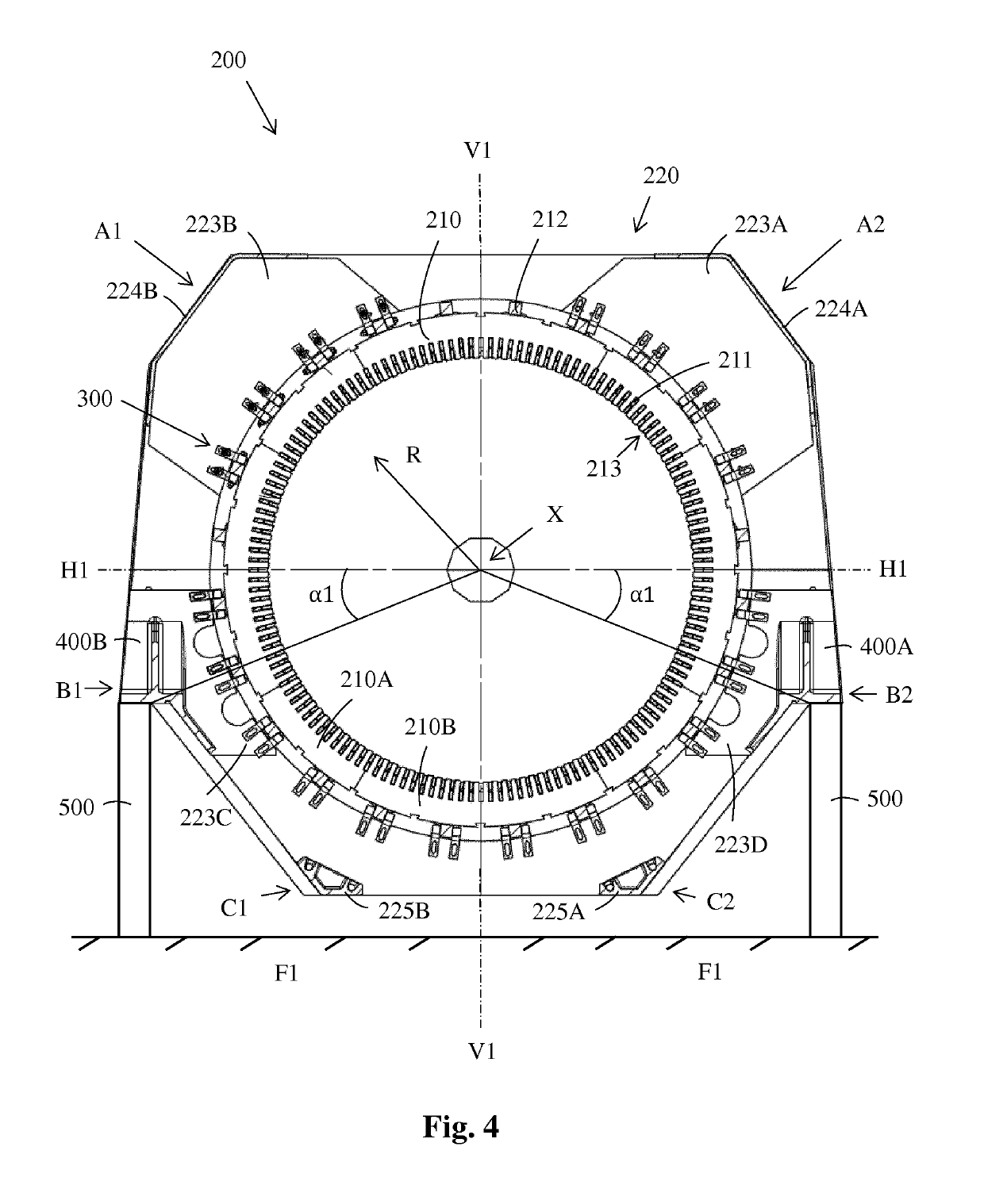
[0054]FIG. 10 shows a fastening bracket that can be used in the fastening arrangements in the electric machine. This fastening bracket 300 comprises a first end 310 and a second end 320. The first end 310 of the fastening bracket 300 comprises two openings 311 and the second end 320 of the fastening bracket 300 comprises one opening 311, which is directed in a direction being perpendicular to the direction of the openings 311 in the first end 310 of the fastening bracket 300. The first end 310 of the fastening bracket 300 can be attached to the stator frame 220 and the second end 320 of the fastening bracket 300 can be attached to the stator core 210 i.e. to the back beam 212.

[0055]The figures show two separate fastening brackets 300 at each side of the back beam 212, but they could naturally be connected to each other e.g. from the top of the first branches 310 of the fastening brackets 300. The two fastening brackets 300 would still form a fastening bracket 300 with two ends i.e. ...

first embodiment

[0056]Each fastening bracket 300 comprises two ends 310, 320. The two ends 310, 320 are formed by two branches 310, 320 in the fastening bracket 300. The two branches 310, 320 are advantageously perpendicular to each other. The two branches 310, 320 have thus the form of a letter L. The essential thing here is that the fastening bracket 300 comprises a first end 310 that can be attached to the stator frame 220 and a second end 320 that can be attached to the stator core 210. The form and the construction of the branches 310, 320 does not as such matter.

[0057]The nut 352 could be provided with friction increasing means in order to prevent loosening of the nut 352 due to vibrations. The fastening means 350 could also be provided with resilient washers under the nut 352 in order to eliminate loosening of the nut 352 due to vibration.

[0058]The embodiment of the stator frame 220 shown in FIG. 6 comprises separate support elements 400A, 400B. This means that each support element 400A, 400...


PUM


Abstract

The electric machine comprises a rotor, a stator surrounding the rotor and a support structure. The stator has a longitudinal center axis and is supported on the support structure with support elements. The stator comprises a cylindrical stator core having a laminated structure and slots for a stator winding and a stator frame surrounding the stator core. The stator frame comprises two opposite end constructions and at least one frame plate located between the end constructions. A support element is located between each end construction and the adjacent frame plate and between adjacent frame plates. The support element is made of cast iron and attached to the end constructions, the frame plate and the support structure with fastening means based on a compression joint, whereby the stator frame becomes attached to the support structure via the support elements.

Description

FIELD OF THE INVENTION[0001]The invention relates to an electric machine according to the preamble of claim 1.[0002]The electric machine comprises a rotor and a stator surrounding the rotor. The stator comprises a longitudinal centre axis, a horizontal centre plane passing through the centre axis of the stator, and a vertical centre plane passing through the centre axis of the stator. The stator comprises further a cylindrical stator core and a stator frame surrounding the stator core. The stator core comprises a laminated structure, a stator winding, and back beams attached to an outer surface of the stator core and extending in the axial direction of the stator. The stator frame comprises two opposite end constructions located at an axial distance from each other.BACKGROUND ART[0003]Electric machines i.e. electric motors and electric generators are used in many applications. Electric motors are used to drive different kinds of machines and electric generators are used to produce e...

Claims


Application Information

Patent Timeline
Patent Type & Authority Patents(United States)
IPC IPC(8): H02K1/18H02K5/02H02K5/04H02K5/26
CPCH02K1/185H02K1/182H02K5/04H02K5/26H02K5/02H02K2213/12
Inventor HELANDER, JOONASGRÜN, MORITZVARTIAINEN, ARI
Owner ABB (SCHWEIZ) AG
Why Eureka
Try Eureka