Heat pump with interleaved evaporator/condenser arrangement

Active Publication Date: 2018-03-15
EFFICIENT ENERGY GMBH
View PDF2 Cites 0 Cited by
  • Summary
  • Abstract
  • Description
  • Claims
  • Application Information

AI Technical Summary

Benefits of technology

[0026]In specific implementations, the evaporator base is configured to comprise connection pipes for the individual feed inlets, which have cross-sections differing from a cross-section of the opening on the other side of the evaporator base. The shape of the individual connection pipes is then configured such that the shape, or cross-sectional shape, changes across the length of the connection pipe, but the pipe diameter, which plays a part in the flow rate, is almost identical with a tolerance of ±10%. In this manner, water flowing through the connection pipe is prevented from starting to cavitate. Thus, on account of the good flow conditions obtained by the shaping of the connection p

Problems solved by technology

In this context one has to take into account, however, that this heat exchanger again represents losses and expenditure in terms of apparatus.
However, one has found that the reduction of the “thickness” of the evaporator space, which tapers within the condenser, is unproblematic since the major part of the evaporation takes place in the lower region, where the evaporator space fills up almost the entire volume available.
On the other hand, the reduction of the thickness

Method used


Image

  • Heat pump with interleaved evaporator/condenser arrangement
  • Heat pump with interleaved evaporator/condenser arrangement
  • Heat pump with interleaved evaporator/condenser arrangement

Examples


Embodiment Construction

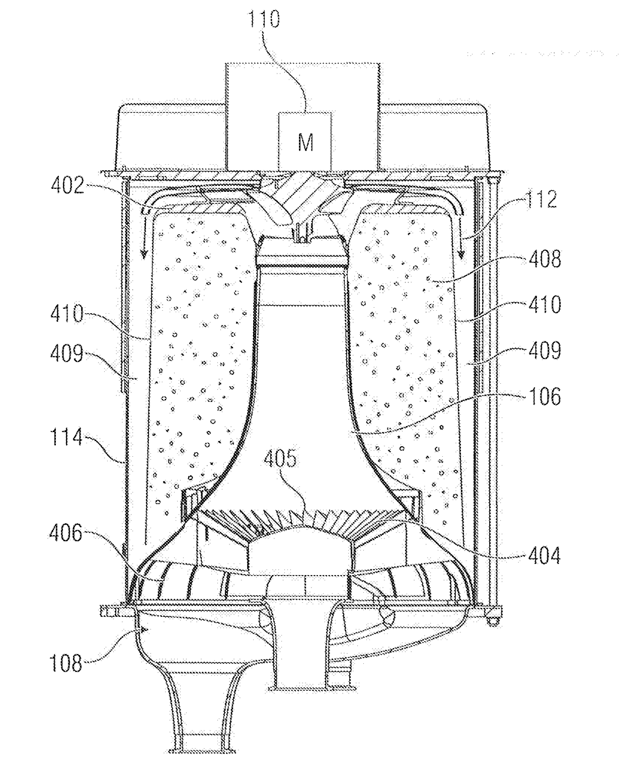
[0047]FIG. 1 shows a heat pump 100 comprising an evaporator for evaporating working liquid within an evaporator space 102. The heat pump further includes a condenser for condensing evaporated working liquid within a condenser space 104 bounded by a condenser base 106. As shown in FIG. 1, which can be regarded both as a sectional representation and as a side view, the evaporator space 102 is at least partially surrounded by the condenser space 104. Moreover, the evaporator space 102 is separated from the condenser space 104 by the condenser base 106. In addition, the condenser base is connected to an evaporator base 108 so as to define the evaporator space 102. In one implementation, a compressor 110 is provided above the evaporator space 102 or at a different location, said compressor 110 not being explained in detail in FIG. 1 but being configured, in principle, to compress evaporated working liquid and to direct same into the condenser space 104 as compressed vapor 112. Moreover, ...


PUM


Abstract

A heat pump includes an evaporator for evaporating working liquid within an evaporator space bounded by an evaporator base, and a condenser for condensing evaporated working liquid within a condenser space bounded by a condenser base, the evaporator space being at least partially surrounded by the condenser space, the evaporator space being separated from the condenser space by the condenser base, and the condenser base being connected to the evaporator base.

Description

CROSS-REFERENCE TO RELATED APPLICATION[0001]This application is a continuation of copending International Application No. PCT / EP2016 / 062060, filed May 27, 2016, which is incorporated herein by reference in its entirety, and additionally claims priority from German Application No. 102015209848.6, filed May 28, 2015, which is incorporated herein by reference in its entirety.[0002]The present invention relates to heat pumps for heating, cooling or for any other application of a heat pump or to an evaporator base for such a heat pump.BACKGROUND OF THE INVENTION[0003]FIG. 8A and FIG. 8B provide a heat pump as is described in European Patent EP 2016349 B1. FIG. 8A shows a heat pump initially comprising a water evaporator 10 for evaporating water as a working liquid so as to generate vapor within a working vapor pipe 12 on the output side. The evaporator includes an evaporation space (evaporation chamber) (not shown in FIG. 8A) and is configured to generate an evaporation pressure smaller ...

Claims


Application Information

Patent Timeline
IPC IPC(8): F25B30/02F25B39/02F25B39/04
CPCF25B30/02F25B39/02F25B39/04F25B2500/18F25B2500/01F25B25/005F25B39/00F25B2339/047
Inventor KNIFFLER, OLIVERSEDLAK, HOLGER
Owner EFFICIENT ENERGY GMBH
Why Eureka
Try Eureka