Syringe pump having a pressure sensor assembly

a technology of pressure sensor and syringe pump, which is applied in the direction of fluid pressure measurement, process and machine control, instruments, etc., can solve the problems of rotational force of securing arm

Active Publication Date: 2019-08-27
DEKA PROD LLP
View PDF442 Cites 44 Cited by
  • Summary
  • Abstract
  • Description
  • Claims
  • Application Information

AI Technical Summary

Benefits of technology

[0259]In some embodiments, the bias force may be created by a spring. Some embodiments may further include sensing the position of the securing arm. Some embodiments of the method may include alerting a user if the securing arm is not properly securing the syringe based on the position of the securing arm. Some embodiments of the method may further include determining at least one characteristic of the syringe using data gleaned from sensing the position of the securing arm. Some embodiments may further include using a processor to determining the fluid flow based on change in position of a plunger of the syringe in conjunction with the determined at least one characteristic of the syringe. Some embodiments may include using data from a plunger driving arm in conjunction with a position of the securing arm to determine at least one characteristic of the syringe. Some embodiments of the method may further include using a processor to determining the fluid flow based on change in position of a plunger in the syringe in conjunction with the determined at least one characteristic of the syringe. In some embodiments a Hall effect sensor is used to sense the position of the securing arm.

Problems solved by technology

When the second arm engages the plate, the force of the spring and the shape of the plate persuades the arm to rotate, ultimately resulting in the rotational force of the securing arm.
The shape of the plate combined with the force of the spring persuades the arm to rotate, ultimately resulting in the rotational force of the securing arm.

Method used


Image

  • Syringe pump having a pressure sensor assembly
  • Syringe pump having a pressure sensor assembly
  • Syringe pump having a pressure sensor assembly

Examples


Embodiment Construction

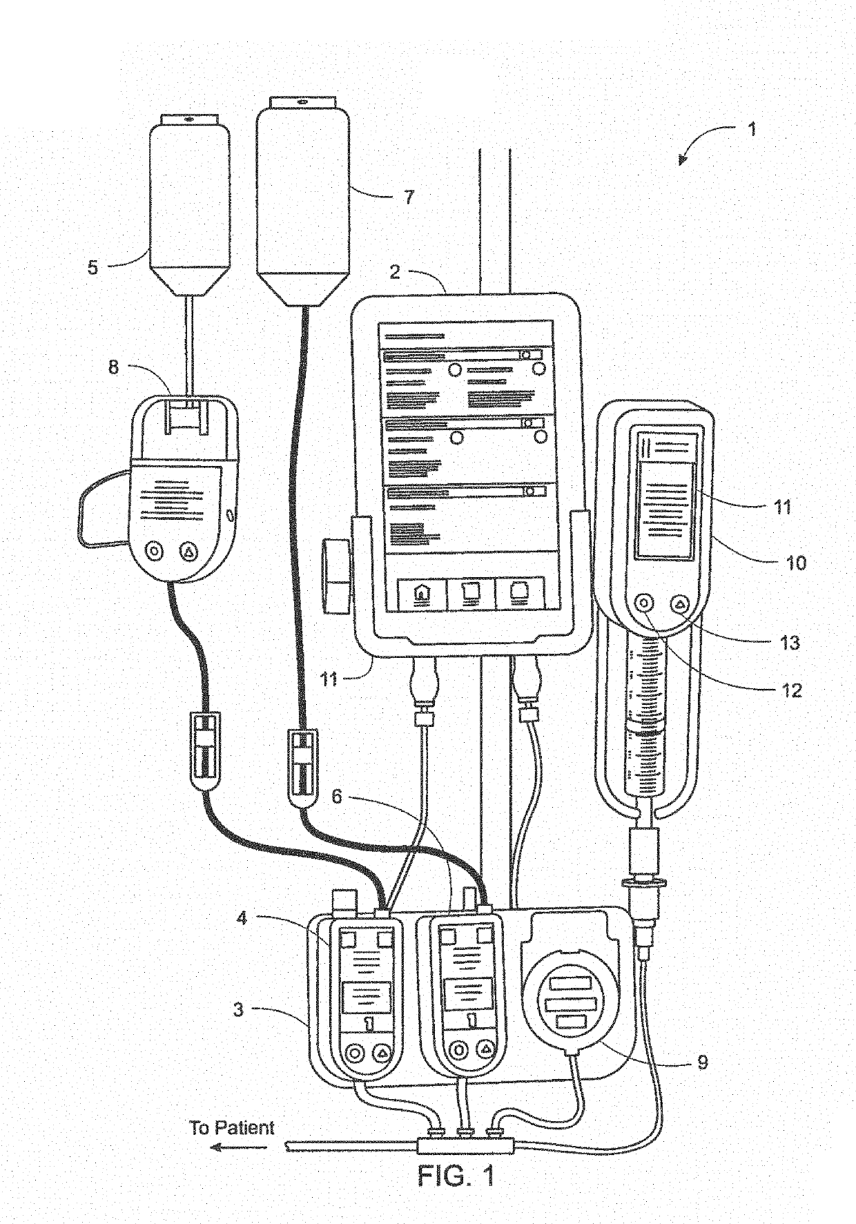
[0463]FIG. 1 shows an exemplary arrangement of a system 1 for electronic patient care in accordance with an embodiment of the present disclosure. The system 1 includes a monitoring client 2 that is linked to a number of patient-care devices via docks 3 and 11, including an infusion pump 4 connected to and delivering from a smaller bag of liquid 5, an infusion pump 6 connected to and delivering from a larger bag of liquid 7, a drip detection device 8 connected to tubing from the smaller bag 5, and a microinfusion pump 9. System 1 also includes a syringe pump 10 connected wirelessly to the monitoring client 2. In some embodiments, the monitoring client 2 may communicate with these patient-care devices in a wired fashion, as shown in FIG. 1 for the infusion pumps 4 and 6, and the microinfusion pump 9 (via docks 3 and 11). Additionally or alternatively, the monitoring client 2 may communicate wirelessly with patient-care devices, as suggested by the absence of a wired connection between...


PUM

PropertyMeasurementUnit
widthaaaaaaaaaa

Abstract

A syringe pump is disclosed that includes a body, a syringe seat, a syringe actuator, a memory, and one or more processors. The syringe seat is coupled to the body. The syringe actuator is configured to actuate a syringe secured within the syringe seat. The memory is configured to store a plurality of instructions. The one or more processors, in accordance with the plurality of instructions, is/are configured to: prime the syringe pump in a prime phase; determine if an occlusion exists during the prime phase using a first test; stop the prime phase; initiate fluid delivery into a patient; enter into a start-up phase; determine if an occlusion exists using a second test during the start-up phase; transition from the start-up phase into a steady-state phase; and determine if an occlusion exists during the steady-state phase using a third test.

Description

CROSS-REFERENCES TO RELATED APPLICATIONS[0001]The present application is a Non-Provisional Application which claims the benefit of U.S. Provisional Patent Application Ser. No. 61 / 942,986, filed Feb. 21, 2014 and entitled Syringe Pump Having a Pressure Sensor Assembly; and U.S. Provisional Patent Application Ser. No. 61 / 990,330, filed May 8, 2014 and entitled Syringe Pump Having a Pressure Sensor Assembly, each of which is hereby incorporated herein by reference in its entirety.[0002]The present application is also a Continuation-In-Part of U.S. patent application Ser. No. 14 / 135,784, filed Dec. 20, 2013 and entitled Syringe Pump, and Related Method and System, now U.S. Publication No. US-2014-0188076-A1, published Jul. 3, 2014, which claims the benefit of U.S. Provisional Patent Application Ser. No. 61 / 904,123, filed Nov. 14, 2013 and entitled Syringe Pump and Related Method; and U.S. Provisional Patent Application Ser. No. 61 / 894,801, filed Oct. 23, 2013 and entitled Syringe Pump a...

Claims


Application Information

Patent Timeline
Patent Type & Authority Patents(United States)
IPC IPC(8): A61M5/168G06F3/0488A61M5/172A61M5/145A61M5/14G01L9/00G01L7/16G16H40/63G16H10/65A61M5/142
CPCA61M5/1408A61M5/1413A61M5/1415A61M5/1452A61M5/1456A61M5/1458A61M5/16827A61M5/16831A61M5/16854A61M2005/14208A61M2005/16872A61M2205/14A61M2205/18A61M2205/3306A61M2205/3317A61M2205/332A61M2205/3368A61M2205/3553A61M2205/3569A61M2205/3576A61M2205/3584A61M2205/50A61M2205/505A61M2205/52A61M2205/581A61M2205/582A61M2205/6063A61M2205/8206A61M2209/082A61M2209/086A61M5/14232A61M2205/12G16H20/17G16H40/63A61M5/172G16H10/65A61M5/16859G01L7/16G01L9/0089G16H40/67G16H70/40G16H20/10A61M2005/16863A61M2209/02G01L9/00G06F3/0488
Inventor DESCH, MARTIN D.GRAY, LARRY B.BODWELL, JESSE T.VAN DER MERWE, DIRK A.
Owner DEKA PROD LLP
Why Eureka
Try Eureka