
LED light tube adapter kit for troffers

a technology of led light tubes and adapters, which is applied in the direction of fixed installation, semiconductor devices of light sources, lighting and heating apparatus, etc., can solve the problems of inability to compete with high-efficiency led (light-emitting diodes) lighting, high cost of replacing existing light fixtures with led light fixtures, and many users simply put up with the inefficiencies of fluorescent lamps. , to achieve the effect of low cost and easy upgrading

Inactive Publication Date: 2019-08-27
CHARTRAND JEAN CLAUDE
View PDF11 Cites 1 Cited by
  • Summary
  • Abstract
  • Description
  • Claims
  • Application Information

AI Technical Summary

Benefits of technology

The patent discusses the problem of reducing energy consumption by upgrading fluorescent lamps in troffers to LED-style lighting at a low cost. The technical effect is to provide a device that allows for easy upgrading of existing troffers with high efficiency LED lighting.

Problems solved by technology

Additionally, air pollution produced by the combustion of fossil fuels is another area of great environmental concern.
While fluorescent lamp troffers are a major improvement over incandescent lamps they cannot compete with high efficiency LED (light-emitting diode) lighting.
While LED lighting is highly energy efficient the cost of replacing existing light fixtures with LED light fixtures has been so high that many users simply put up with the inefficiencies of fluorescent lamps.
While such retrofit kits can be beneficial they are typically difficult and time consuming to install and usually do not afford the user with the ability to increase or decrease the number of light tubes to compensate for the increased efficiency of LED lamps.

Method used


Image

  • LED light tube adapter kit for troffers
  • LED light tube adapter kit for troffers
  • LED light tube adapter kit for troffers

Examples


Embodiment Construction

[0062]The preferred embodiment of the present invention is depicted in FIGS. 1 through 6. However, the invention is not limited to the specifically described embodiment. A person skilled in the art will appreciate that many other embodiments of the invention are possible without deviating from the basic concept of the invention. Any such work around will also fall under the scope of this invention.

[0063]In the figures like numbers refer to like elements throughout. Additionally, the terms “a” and “an” as used herein do not denote a limitation of quantity, but rather denote the presence of at least one (1) of the referenced items.

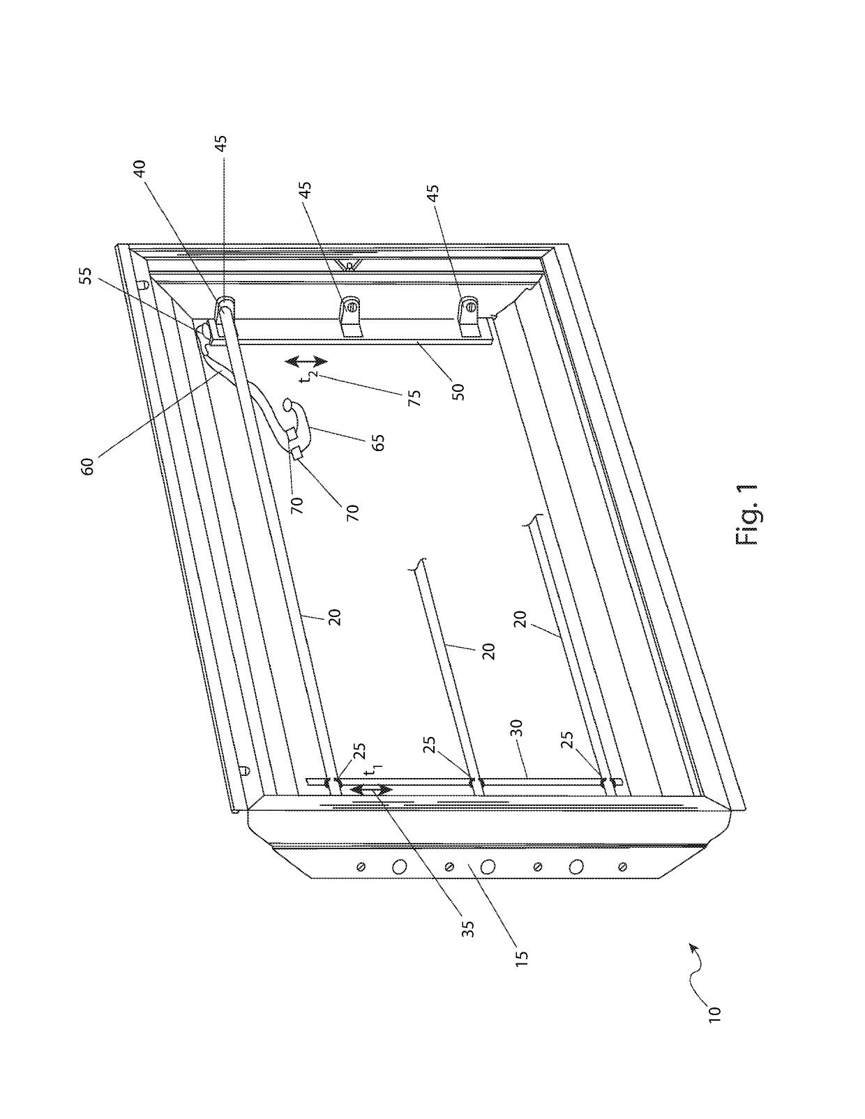
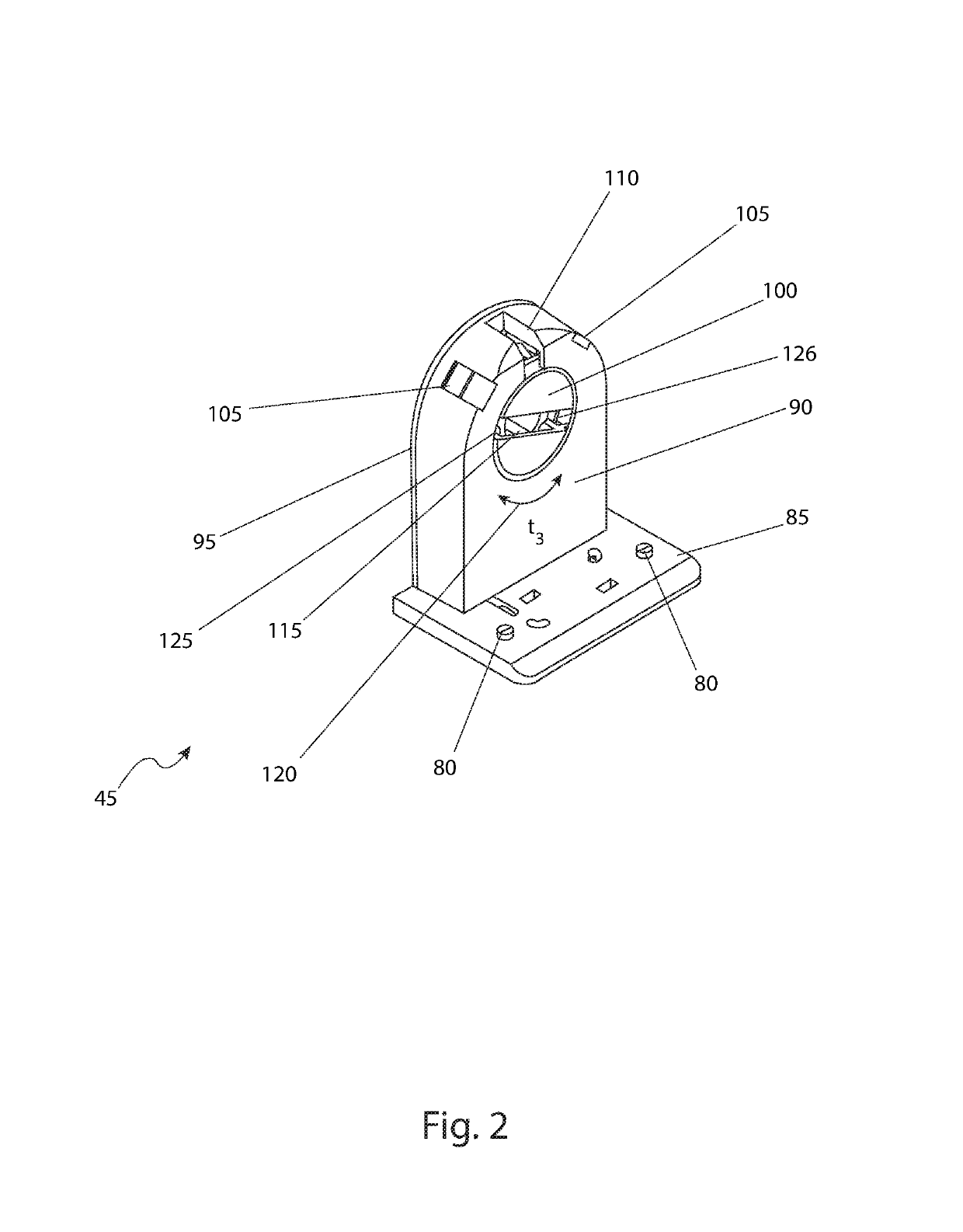
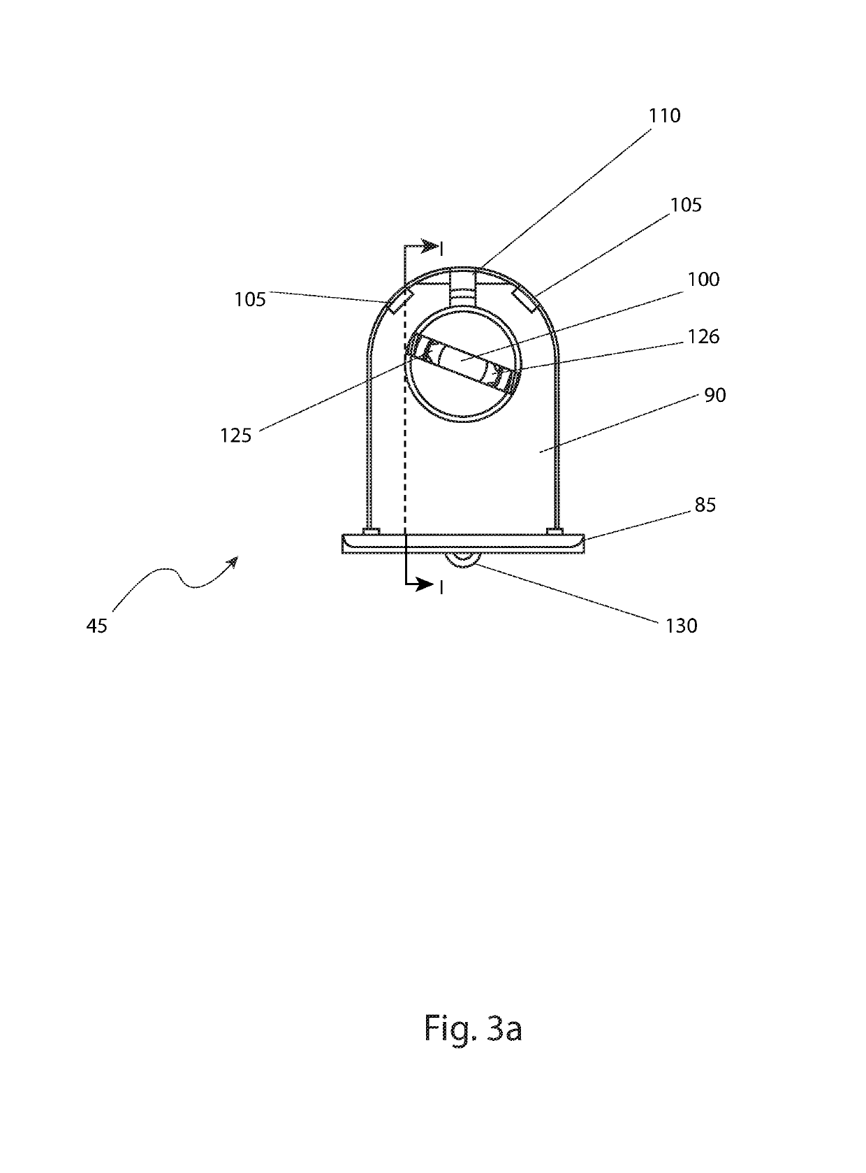
[0064]Refer now to FIG. 1 for an isometric view of a LED light tube adapter kit for a fluorescent troffer fixture 10 installed in an existing fluorescent troffer fixture 15 in accord with a preferred embodiment of the present invention. The illustrated fluorescent troffer fixture 15 is a conventional troffer style fluorescent ceiling such as those that would...


PUM


Abstract

A light tube adapter kit for converting fluorescent troffers to use LED light tubes is provided. The adapter kit includes a light tube having electrical connector prongs at a connector end, a troffer fixture, a non-powered adjustment mechanically connected to the troffer fixture, a powered adjustment strip disposed across and connected to the troffer fixture, a retention clip that mechanically attaches a first end of the light tube to the non-powered adjustment clip, and a tombstone fixture that is electrically connected to the powered adjustment strip. The tombstone fixture mechanically retains a powered end of the light tube and transfers electrical power from the powered adjustment strip to the connector prongs.

Description

RELATED APPLICATIONS[0001]The present invention is a continuation-in-part of, was first described in and claims the benefit of U.S. Provisional Application No. 62 / 289,374 filed Feb. 1, 2016, the entire disclosures of which are incorporated herein by reference.FIELD OF THE INVENTION[0002]The present invention relates generally to converting florescent tube troffers to use LED (light-emitting diode) light sources.BACKGROUND OF THE INVENTION[0003]Concerns over the limited supply of fossil fuels have generated a great deal of research and engineering work in the area of alternative fuel and energy sources. Additionally, air pollution produced by the combustion of fossil fuels is another area of great environmental concern. The concerns related to fossil fuels impact on many things that we do, from driving automobiles to recycling consumer products.[0004]One (1) area that has received particular attention is that of reducing energy consumption used by illumination sources. Fluorescent la...

Claims


Application Information

Patent Timeline
Patent Type & Authority Patents(United States)
IPC IPC(8): F21S8/02F21V17/16F21V23/00F21K9/275F21V15/01F21V23/06F21K9/278F21V3/02
CPCF21K9/27F21S8/026F21V23/06F21Y2115/10Y02B20/30F21K9/275F21K9/278F21V3/02F21V15/01F21V17/16F21V23/001
Inventor CHARTRAND, JEAN-CLAUDE
Owner CHARTRAND JEAN CLAUDE
Learn More