Method for calibrating an optical arrangement

a technology for optical arrangements and calibration methods, applied in closed circuit television systems, instruments, measurement devices, etc., can solve the problems of limited calibration accuracy, inability to measure whole-area distortion, and high cost of plane plates, and achieve the effect of convenient implementation

Inactive Publication Date: 2019-09-03
CARL ZEISS IND MESSTECHN GMBH
View PDF39 Cites 1 Cited by
  • Summary
  • Abstract
  • Description
  • Claims
  • Application Information

AI Technical Summary

Benefits of technology

[0006]It is therefore an object of the present invention to provide a method for calibrating an optical arrangement of the type mentioned at the outset, which can easily be implemented.
[0007]It is another object of the invention to provide a method for calibrating an optical arrangement that can be implemented cheaper and with less effort.
[0008]It is yet another object of the invention to provide a coordinate measuring machine having an optical arrangement comprising a camera and a projector, which can conveniently be calibrated with high accuracy.

Problems solved by technology

However, such plane plates are expensive.
Moreover, a whole-area distortion measurement is not possible with such an arrangement, and so the accuracy of the calibration is limited.
Another disadvantage afflicting the aforementioned known methods is that these require a plurality of calibration steps with different components, the spatial assignment of which is only possible with much effort.

Method used


Image

  • Method for calibrating an optical arrangement
  • Method for calibrating an optical arrangement
  • Method for calibrating an optical arrangement

Examples


Embodiment Construction

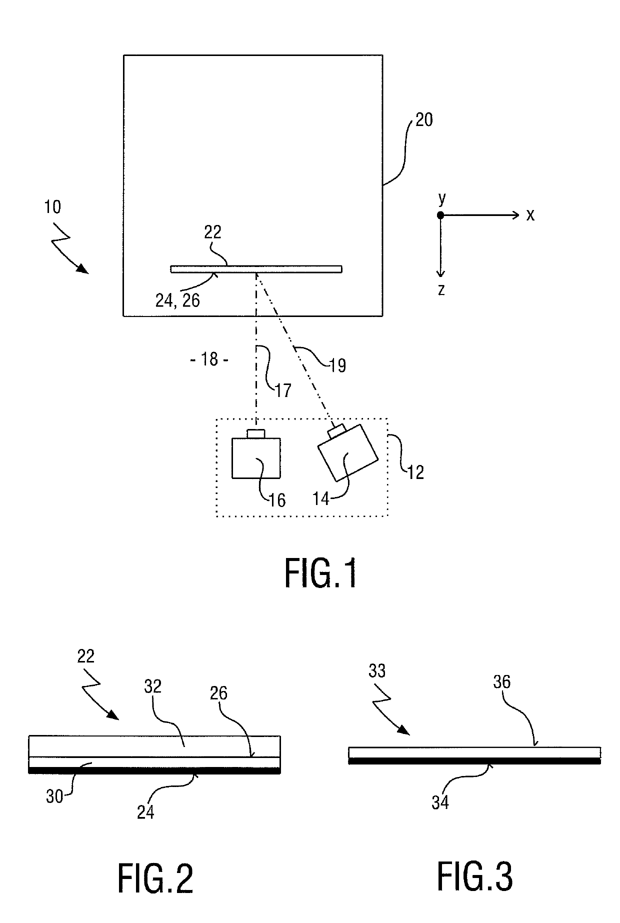
[0080]FIG. 1 shows a schematic set up of a calibration system, provided with the general reference sign 10, in accordance with an exemplary embodiment. The calibration system 10 comprises an optical arrangement 12 comprising a projector 14 and a camera 16.

[0081]The projector 14 is designed to project a first pattern onto a projection area 24, which is arranged in a measurement volume 18. As shown in FIG. 1, the projection area 24 is embodied as a matte surface on a display 22 of an electronic device, for example a cellular telephone or computer.

[0082]The camera 16 is designed to detect a second pattern displayed on a display area 26 of a display element. As shown in an exemplary manner in FIG. 1, the display element is the display 22, wherein the display area 26 is arranged on the same side of the display 22 as the matte projection area 24, to be precise in such a way that the display area 26 is aligned towards the camera 16. Preferably, the display area 26 is a display surface of t...


PUM


Abstract

A method for calibrating an optical arrangement for determining dimensional properties of a measurement object and a coordinate measuring machine implementing the method are disclosed. The optical arrangement has a camera and a projector for projecting a first periodic pattern onto a projection area. The optical arrangement is moveable relative to a workpiece table along a first axis. A matte surface is arranged on the workpiece table at a first position relative to the optical arrangement. A second periodic pattern, which is separate from the first periodic pattern, is provided and shifted on the matte surface. Images of the second pattern are recorded using the camera and at least one distortion aberration of the camera is determined using the second periodic pattern. The first periodic pattern is projected onto the matte surface and first and second coordinates of at least one pattern point of the projected first periodic pattern are determined, the second coordinate with respect to a second axis, which is perpendicular to the first axis. The matte surface is displaced relative to the optical arrangement to a second position along the first axis and the aforementioned steps are repeated for a plurality of relative positions of the matte surface along the first axis.

Description

CROSS-REFERENCES TO RELATED APPLICATIONS[0001]This application claims Paris Convention priority from German patent application 10 2016 110 802.2 filed on Jun. 13, 2016 with the German Patent and Trademark Office. The entire content of this priority application is incorporated herein by reference.BACKGROUND OF THE INVENTION[0002]The invention relates to a method for calibrating an optical arrangement comprising a camera and a projector. The invention further relates to a coordinate measuring machine having such an optical arrangement and implementing the calibration method.[0003]A method of the afore-mentioned type is disclosed by DE 195 36 297 A1. A projector is used to project a predetermined pattern onto a projection area which, for example, is on a calibration plate. The projection area or the calibration plate is introduced into the measurement volume in advance. Then, a coordinate with respect to a first axis in the coordinate system of the measurement volume is determined for ...

Claims


Application Information

Patent Timeline
Patent Type & Authority Patents(United States)
IPC IPC(8): G01B11/00G01B21/04G01B11/25H04N7/18
CPCG01B11/005G01B21/042G01B11/2504H04N7/18G01B11/25G01B11/254
Inventor HOELLER, FRANKPAUL, OLIVERWIDULLE, FRANK
Owner CARL ZEISS IND MESSTECHN GMBH
Why Eureka
Try Eureka