
Method for detecting pseudo-3D bounding box based on CNN capable of converting modes according to poses of objects using instance segmentation and device using the same

a pseudo-3d bounding box and object technology, applied in the field of learning methods, learning devices, testing methods and testing devices for use with autonomous vehicles, can solve the problems of consuming a lot of computational time, consuming a lot of computational resources, and requiring conventional methods to acquire 3d bounding boxes. to achieve the effect of reducing computational time and resources

Active Publication Date: 2019-09-03
STRADVISION
View PDF2 Cites 9 Cited by
  • Summary
  • Abstract
  • Description
  • Claims
  • Application Information

AI Technical Summary

Benefits of technology

The patent aims to save time and resources by using 2D coordinates of vertices in a pseudo-3D box. The technical effect is faster and more efficient computing.

Problems solved by technology

Then, a 3D bounding box is constructed from the determined anchor box, however, there are limitations.
Second, in case a single template is used for determining the three surfaces of the 3D bounding box, an accuracy may be low because boundary conditions of regression may vary as 3D orientation of the object changes.
Third, conventional methods of acquiring the 3D bounding box require much computational resources.
For example, matching a cuboid template or voxel for finding a 3D bounding box takes up a lot of computational time.

Method used


Image

  • Method for detecting pseudo-3D bounding box based on CNN capable of converting modes according to poses of objects using instance segmentation and device using the same
  • Method for detecting pseudo-3D bounding box based on CNN capable of converting modes according to poses of objects using instance segmentation and device using the same
  • Method for detecting pseudo-3D bounding box based on CNN capable of converting modes according to poses of objects using instance segmentation and device using the same

Examples


Embodiment Construction

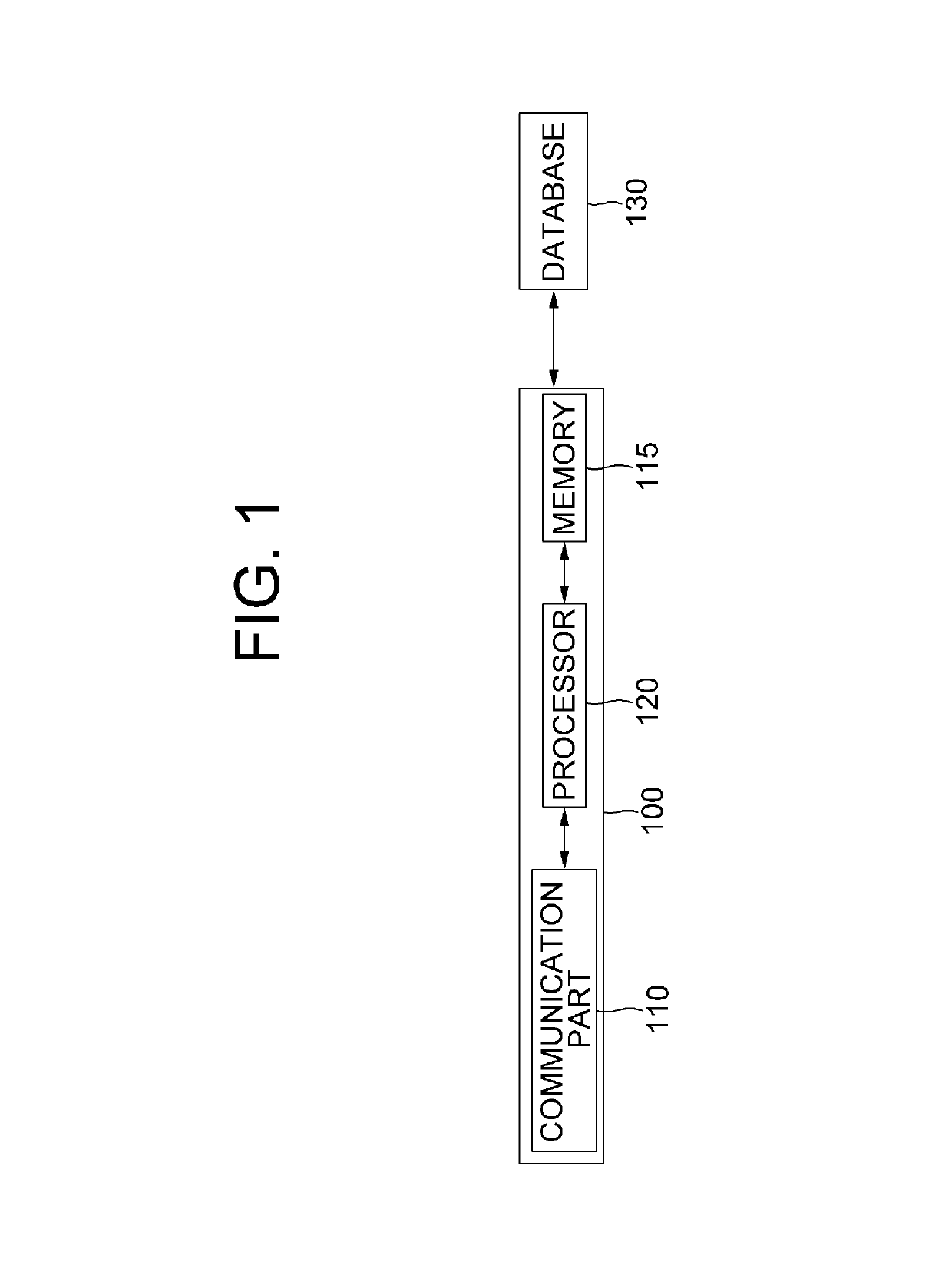
[0052]Detailed explanation on the present disclosure to be made below refer to attached drawings and diagrams illustrated as specific embodiment examples under which the present disclosure may be implemented to make clear of purposes, technical solutions, and advantages of the present disclosure. These embodiments are described in sufficient detail to enable those skilled in the art to practice the disclosure.

[0053]Besides, in the detailed description and claims of the present disclosure, a term “include” and its variations are not intended to exclude other technical features, additions, components or steps. Other objects, benefits, and features of the present disclosure will be revealed to one skilled in the art, partially from the specification and partially from the implementation of the present disclosure. The following examples and drawings will be provided as examples but they are not intended to limit the present disclosure.

[0054]Moreover, the present disclosure covers all po...


PUM


Abstract

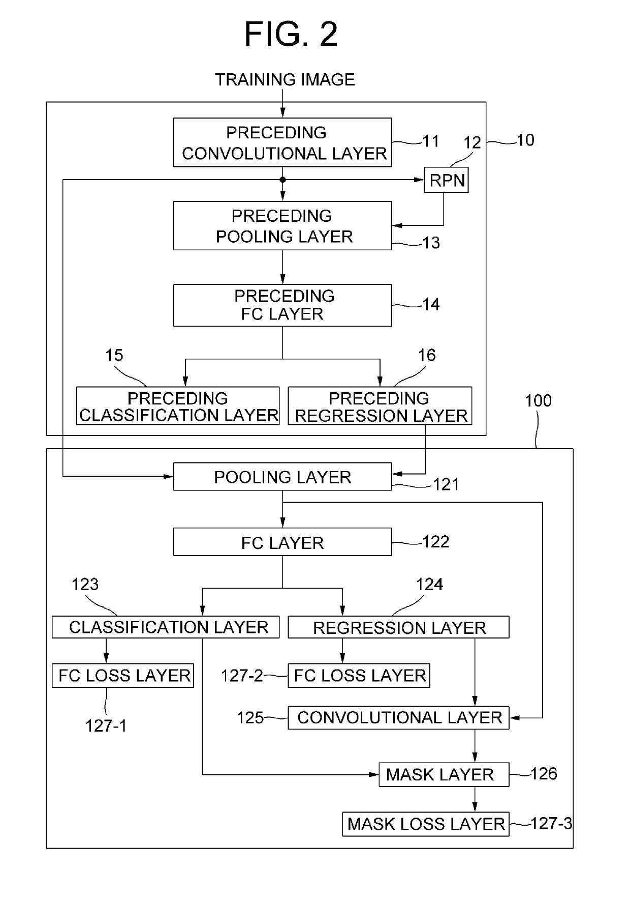
A method for detecting a pseudo-3D bounding box based on a CNN capable of converting modes according to poses of detected objects using an instance segmentation is provided to be used for realistic rendering in virtual driving. Shade information of each of surfaces of the pseudo-3D bounding box can be reflected on the learning according to this method. The pseudo-3D bounding box may be obtained through a lidar or a rader, and the surface may be segmented by using a camera. The method includes steps of: a learning device instructing a pooling layer to apply pooling operations to a 2D bounding box region, thereby generating a pooled feature map, and instructing an FC layer to apply neural network operations thereto; instructing a convolutional layer to apply convolution operations to surface regions; and instructing a FC loss layer to generate class losses and regression losses.

Description

FIELD OF THE DISCLOSURE[0001]The present disclosure relates to a learning method, a learning device, a testing method and a testing device for use with an autonomous vehicle; and more particularly, to the learning method and the learning device for detecting at least one pseudo-3D bounding box based on a CNN, and the testing method and the testing device using the same.BACKGROUND OF THE DISCLOSURE[0002]An autonomous car is a vehicle that is capable of sensing its environment and navigating without human input. Autonomous cars use a variety of techniques to detect their surroundings, such as radar, laser light, GPS, odometry, and computer vision.[0003]Estimating three-dimensional (3D) information from two-dimensional (2D) monocular images by using the computer vision is an important task in applications such as autonomous driving and personal robotics. In general, a 2D box for bounding an object in an image is created and then a 3D model is constructed from the 2D box.[0004]To find t...

Claims


Application Information

Patent Timeline
Patent Type & Authority Patents(United States)
IPC IPC(8): G06K9/00G06T7/73G06T7/11G06K9/62
CPCG06K9/6232G06T7/11G06T7/73G06K9/6267G06K9/6262G06T2207/20084G06T2207/20081G06T7/13G06T2207/10028G06F18/241G06T2207/10004G06T2207/20021G06T2207/30261G06V20/64G06V10/255G06V10/454G06V2201/08G06V10/82G06N3/084G06N3/04G06V20/56G06F18/24G06F18/217
Inventor KIM, KYE-HYEONKIM, YONGJOONGKIM, INSUKIM, HAK-KYOUNGNAM, WOONHYUNBOO, SUKHOONSUNG, MYUNGCHULYEO, DONGHUNRYU, WOOJUJANG, TAEWOONGJEONG, KYUNGJOONGJE, HONGMOCHO, HOJIN
Owner STRADVISION
Learn More