Requirements-based test generation

a technology of requirements and test results, applied in the field of requirements-based test results, can solve the problems of futile further test generation and reduce the time and resources needed for verification, and achieve the effect of facilitating the achievement of do-178b objectives and reducing time and resources

Active Publication Date: 2010-01-05
HONEYWELL INT INC
View PDF7 Cites 36 Cited by
  • Summary
  • Abstract
  • Description
  • Claims
  • Application Information

AI Technical Summary

Benefits of technology

[0003]In general, the present invention relates to verification using models for systems that will eventually be implemented in some combination of software and hardware, such as those used for aviation. The objective is to verify that the implementation complies with the model, using test cases created from information in the model. This test generation method facilitates meeting DO-178B objectives by generating tests at several levels of design. A test driver, or test harness, may use these test cases to verify the software and requirements embodied in the model and, in so doing, may achieve structural code coverage. Because application developers currently use costly inspection procedures and manual test generation to meet DO-178B objectives, this automation of the process can dramatically reduce the time and resources needed for verification.

Problems solved by technology

Because application developers currently use costly inspection procedures and manual test generation to meet DO-178B objectives, this automation of the process can dramatically reduce the time and resources needed for verification.
A static analysis phase determines if the diagram contains any static errors; typically, static errors—such as design errors and untestable conditions—render any further test generation futile, and a developer would generally be prompted to fix these errors before further processing occurs.

Method used


Image

  • Requirements-based test generation
  • Requirements-based test generation
  • Requirements-based test generation

Examples


Embodiment Construction

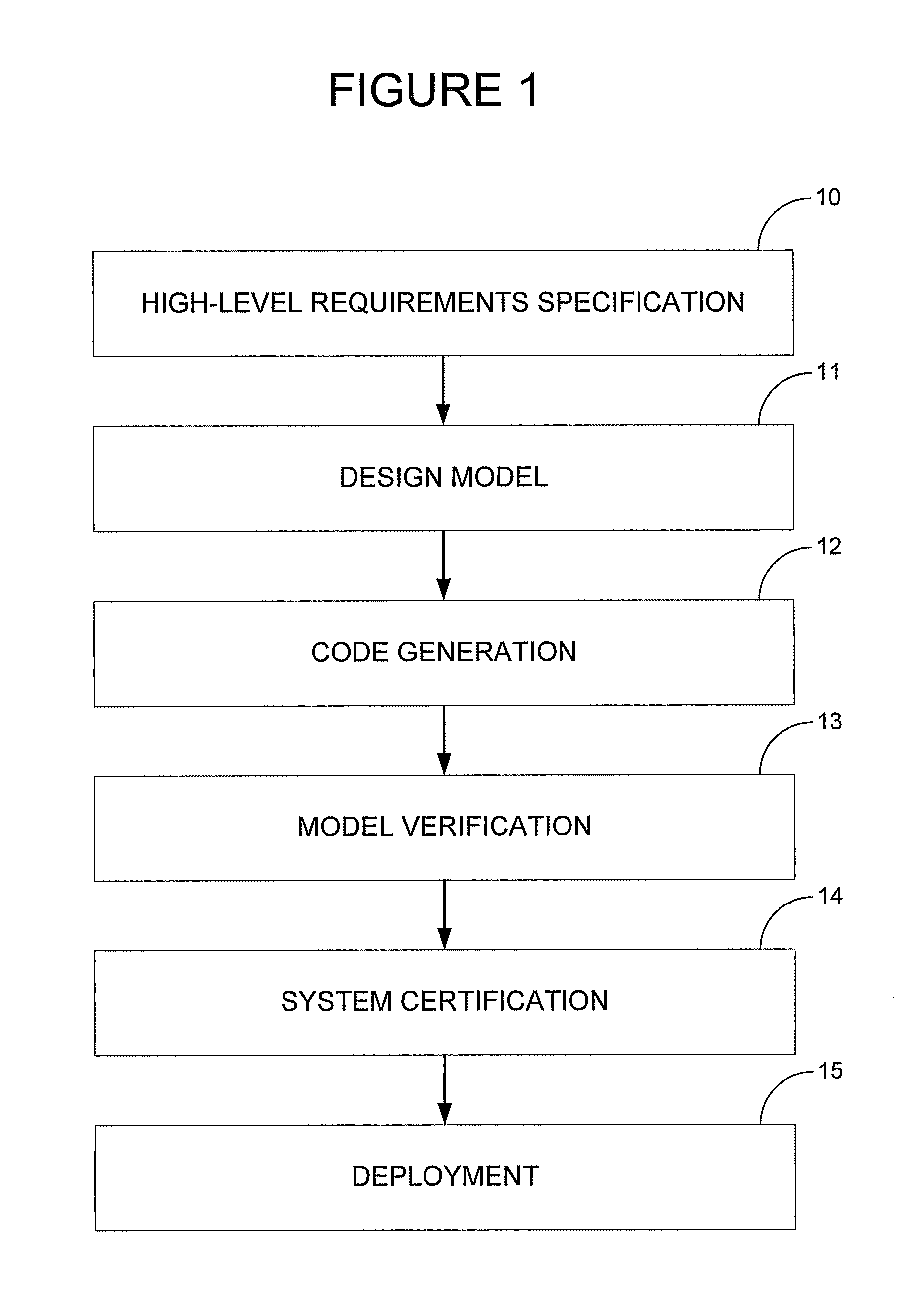
[0013]This invention relates to the development and verification of systems designed using models and to be implemented in a combination of software and hardware. It should be understood that variations in form and detail may be made to the invention without deviating from the spirit and scope of the invention.

[0014]Implementation verification is one aspect of the overall development process for systems. As an example, FIG. 1 generally charts the development process of control systems. In step 10, a developer identifies a problem such as the need for a particular type of navigation control system and specifies high-level functional requirements for solving the problem. The developer correspondingly proceeds with the design of a system model in step 11, probably in collaboration with a team of developers. The result of step 11 is likely to be a functional model of a system that solves the problem specified in step 10.

[0015]In step 12, code may be generated from the model, either manu...


PUM


Abstract

This test generator takes data flow block diagrams and uses requirements-based templates, selective signal propagation, and range comparison and intersection to generate test cases containing test vectors for those diagrams. The templates are based on the functionality and characteristics of a block type, and each block type has associated templates. These templates provide maps for the creation of test values that verify the functionality of particular instances of that block type. Signal propagation allows the generation of diagram-level test cases that verify particular characteristics of a single embedded block. The methods disclosed for signal propagation utilize range intersection, equivalence classes, and block type formulae to create efficient and complete test cases. This test generation method would preferably be repeated until all blocks in a data flow block diagram were verified in their respective contexts, and it creates test cases that cover multiple time steps.

Description

PRIORITY[0001]This application claims priority to and incorporates by reference the entirety of U.S. Provisional Application No. 60 / 861,121, “Requirements-Based Test Generation Using Signal Propagation and Range Intersection,” filed on Nov. 27, 2006.BACKGROUND OF THE INVENTIONDescription of the Problem[0002]Verification of algorithm implementations is extremely costly, particularly for aerospace applications that need to be certified. Most of the verification efforts and costs are in testing a software implementation against its design specifications; by automating this verification process, the test generator described herein can substantially reduce the cost and cycle time of system development and certification. This automated test generation is possible due to the widespread industry practice of capturing the software design as a model (data flow block diagram) using tools such as Matlab. The DO-178B certification standard used by the FAA is one example of an industry requiremen...

Claims


Application Information

Patent Timeline
Patent Type & Authority Patents(United States)
IPC IPC(8): G01R31/28
CPCG01R31/31704G06F11/261G01R31/318364G01R31/318357G06F11/3684
Inventor HICKMAN, STEPHEN O.BHATT, DEVESH
Owner HONEYWELL INT INC
Why Eureka
Try Eureka