High-frequency delay-locked loop and clock processing method for same

a clock processing method and delay-locked loop technology, applied in the field of delay-locked loops, can solve the problems of inability to obtain predetermined output clocks and disappearing high levels

Active Publication Date: 2019-09-03
XI AN UNIIC SEMICON CO LTD
View PDF16 Cites 0 Cited by
  • Summary
  • Abstract
  • Description
  • Claims
  • Application Information

AI Technical Summary

Benefits of technology

[0009]In view of the problems existing in the prior art, the present invention provides a high-frequency delay-locked loop that can ensure that a clock signal is stable and does not disappear even for a clock signal having a high-frequency and a small receivable duty cycle, and a clock processing method for same.
[0019]Compared with the prior art, the present invention has the following advantageous technical effects:
[0020]The present invention adjusts the pulse width of the input clock to a fixed pulse width by providing the pulse generating circuit, so that the input clock has enough pulse width during transmission without causing the disappearance of signal due to the distortion, guaranteeing that the clock signal is not lost when transmitted in the DLL delay chain and the DCC delay chain. Meanwhile, because only the width of the pulse signal is changed but the period and the phase are not changed, the interference with the signal and the damage to the signal are avoided, and the stability and reliability of signal transmission are ensured while the transmission quality is improved. The present invention can be used widely.
[0021]Further, by making the input clock delayed, the rising edge and falling edge of the fixed pulse width are generated by using the pulses of the input clock itself, and thus the width of the fixed pulse can be controlled by only controlling the delay time without introducing an external signal, making the circuit structure simple.

Problems solved by technology

That is, after the clock with a high level of 300 ps is delayed, the high level will disappear and a predetermined output clock cannot be obtained.

Method used


Image

  • High-frequency delay-locked loop and clock processing method for same
  • High-frequency delay-locked loop and clock processing method for same

Examples


Embodiment Construction

[0027]The present invention will further be described in details with reference to specific examples, and it is to be understood that the following description is intended to be illustrative of the invention and not to limit the invention.

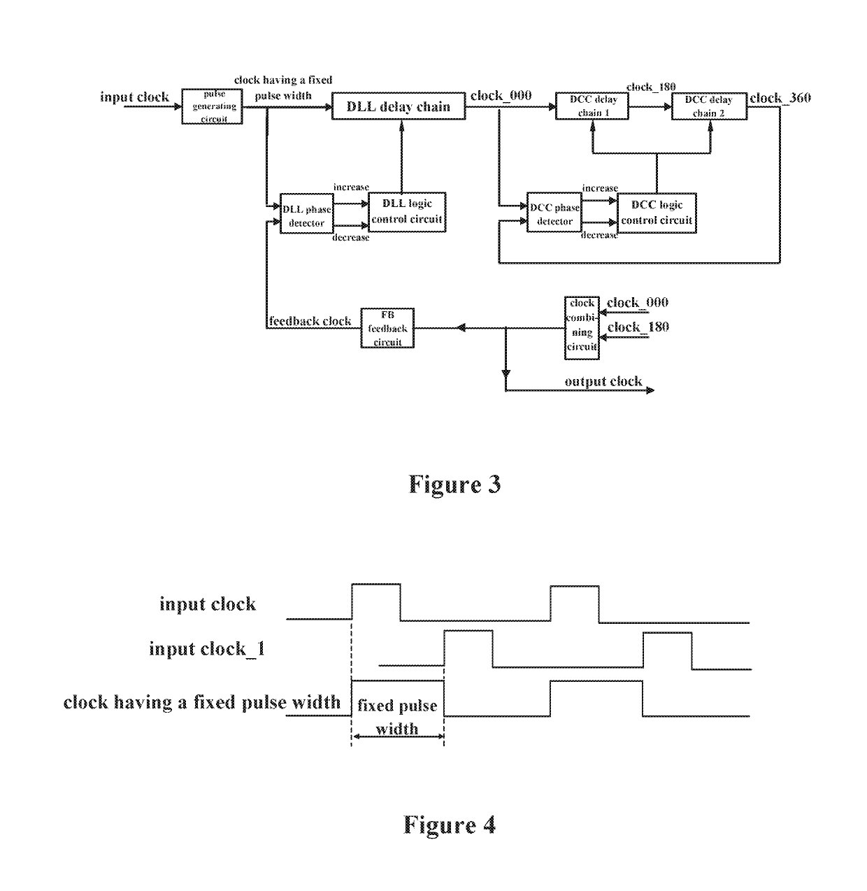
[0028]FIG. 3 shows a schematic diagram of a high-frequency delay-locked loop circuit structure according to one embodiment of the present invention. As shown in FIG. 3, the high-frequency delay-locked loop circuit includes a DLL circuit and a DCC circuit that are sequentially connected in series, and a pulse generating circuit; an input clock accesses the input of the DLL circuit via the pulse generating circuit; the pulse generating circuit is used for generating a clock having a fixed pulse width, the fixed pulse width is not smaller than the minimum pulse width required by the DLL circuit and the clock having the fixed pulse width is input into the DLL circuit. The operation principle of the pulse generating circuit will be described below with ...


PUM


Abstract

The present invention provides a high-frequency delay-locked loop and a clock processing method for the high-frequency delay-locked loop. The high-frequency delay-locked loop comprises a DLL circuit and a DCC circuit that are sequentially connected in series, and a pulse generating circuit used for generating a clock having a fixed pulse width. The fixed pulse width is a high-level width of the clock having the fixed pulse width and not smaller than a minimum pulse width required by the DLL circuit. The fixed pulse width enables a low-level width of the clock having the fixed pulse width to be not smaller than the minimum pulse width required by the DLL circuit. The clock having the fixed pulse width is input into the DLL circuit.

Description

CROSS-REFERENCE TO RELATED APPLICATIONS[0001]The present application is a U.S. National Phase Application of International Application No. PCT / CN2015 / 091198, filed Sep. 30, 2015, which claims priority to Chinese Application No. 201410522694.5, filed Sep. 30, 2014, each of which are hereby incorporated by reference in their entirety.TECHNICAL FIELD[0002]The present invention relates to a delay-locked loop, and more particularly relates to a high-frequency delay-locked loop and a clock processing method for the high-frequency delay-locked loop.BACKGROUND ART[0003]The delay-locked loop (DLL) technology, which is achieved by improving the PLL technology, is widely applied in the timing field. The DLL has inherited the phase lock technology for PLL circuit, but removed the oscillator section within the PLL circuit, which is replaced by a delay line whose delay amount can be controlled. Compared with the PLL, the DLL has no jitter accumulation, but has a shorter locking time and the advan...

Claims


Application Information

Patent Timeline
Patent Type & Authority Patents(United States)
IPC IPC(8): H03K7/08H03L7/081H03L7/08
CPCH03K7/08H03L7/08H03L7/0812
Inventor MINZONI, ALASSANDRO
Owner XI AN UNIIC SEMICON CO LTD
Why Eureka
Try Eureka