Optical transport system employing direct-detection self-coherent receivers and compatible transmitters

a technology of optical transport system and receiver, applied in the field of optical communication equipment, can solve the problem of limiting the maximum transmission distance achievable in some direct-detection systems

a technology of optical transport system and receiver, applied in the field of optical communication equipment, can solve the problem of limiting the maximum transmission distance achievable in some direct-detection systems

US10404400B2Inactive Publication Date: 2019-09-03NOKIA OF AMERICA CORP

Image

  • Optical transport system employing direct-detection self-coherent receivers and compatible transmitters
  • Optical transport system employing direct-detection self-coherent receivers and compatible transmitters
  • Optical transport system employing direct-detection self-coherent receivers and compatible transmitters

Examples


Embodiment Construction

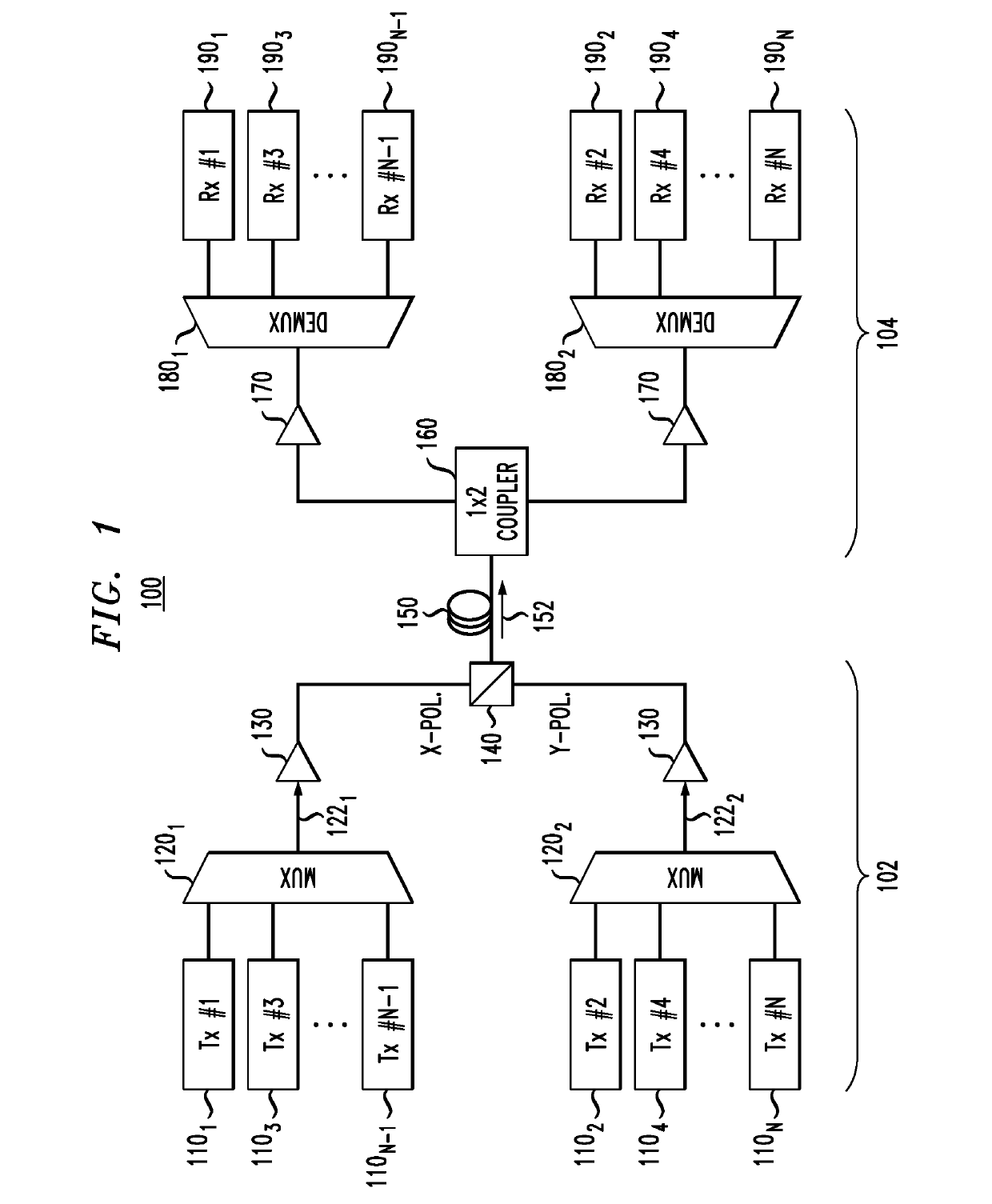
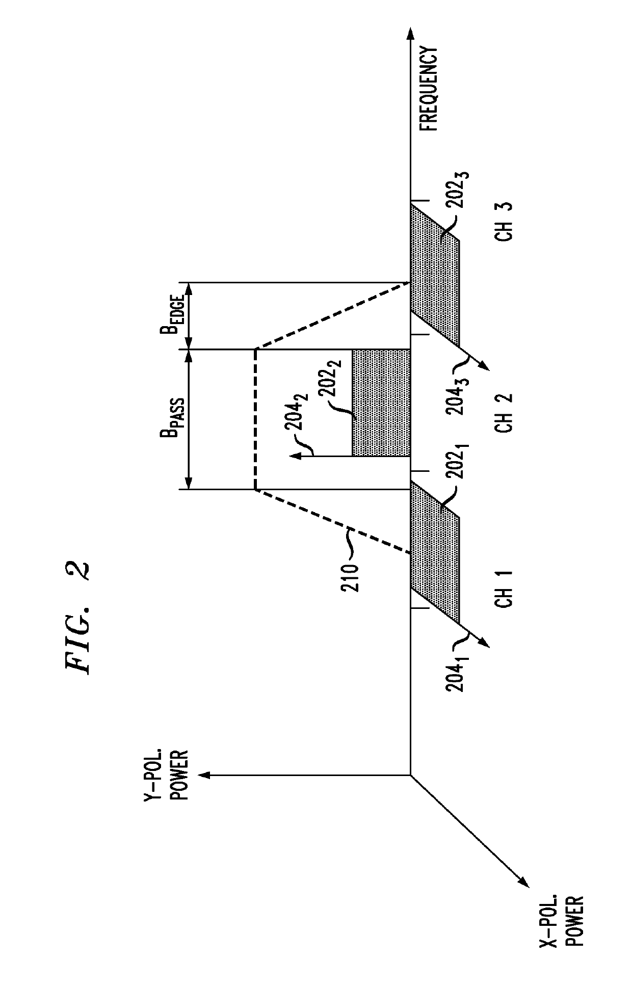
[0005]Disclosed herein are various embodiments of an optical WDM system configured to use direct (square-law) detection of communication signals that is compatible with electronic CD compensation on a per-channel basis. In an example embodiment, to enable full (e.g., amplitude and phase) electric-field reconstruction at the receiver, the optical WDM system uses a carrier-frequency plan according to which the carrier-frequency comb used at one end of the WDM link and the carrier-frequency comb used at the other end of the WDM link are offset with respect to one another by one half of the bandwidth of an individual WDM component transmitted therethrough. This frequency offset places each local carrier frequency at a roll-off edge of the corresponding incoming data-modulated signal. As a result, the corresponding combined optical signal beneficially lends itself to direct detection that can be followed by full electric-field reconstruction using a known self-coherent Kramers-Kronig met...


PUM


Abstract

An optical WDM system configured to use direct detection of communication signals that is compatible with electronic CD compensation on a per-channel basis. In an example embodiment, to enable full (e.g., amplitude and phase) electric-field reconstruction at the receiver, the optical WDM system uses a carrier-frequency plan according to which the carrier-frequency comb used at one end of the WDM link and the carrier-frequency comb used at the other end of the WDM link are offset with respect to one another by one half of the bandwidth of an individual WDM component transmitted therethrough. This frequency offset places each local carrier frequency at a roll-off edge of the corresponding incoming data-modulated signal. As a result, the corresponding combined optical signal beneficially lends itself to direct detection that can be followed by full electric-field reconstruction using a known self-coherent Kramers-Kronig method and then by conventional electronic CD compensation.

Description

CROSS-REFERENCE TO RELATED APPLICATIONS[0001]This application claims the benefit of U.S. Provisional Patent Application No. 62 / 483,134 filed on 7 Apr. 2017, and entitled “OPTICAL TRANSPORT SYSTEM EMPLOYING DIRECT-DETECTION COHERENT RECEIVERS AND COMPATIBLE TRANSMITTERS,” which is incorporated herein by reference in its entirety.BACKGROUNDField[0002]The present disclosure relates to optical communication equipment and, more specifically but not exclusively, to an optical transport system employing direct-detection self-coherent receivers and compatible transmitters.Description of the Related Art[0003]This section introduces aspects that may help facilitate a better understanding of the disclosure. Accordingly, the statements of this section are to be read in this light and are not to be understood as admissions about what is in the prior art or what is not in the prior art.[0004]For relatively short (e.g., ˜100 km) optical links encountered in metro-area networks, direct (e.g., squar...

Claims


Application Information

Patent Timeline
03 Sep 2019
Publication
US10404400B2
IPC
H04B10/40; H04B10/61; H04J14/00; H04J14/06; H04J14/02
CPC
H04B10/40; H04J14/002; H04J14/06; H04J14/0227; H04B10/611; H04B10/65
Inventors
CHEN, XI; SETHUMADHAVAN, CHANDRASEKHAR