Electrical receptacle connector with an enhanced structural strength of a tongue

a technology of electrical receptacle connector and tongue, which is applied in the direction of coupling device connection, two-part coupling device, electrical apparatus, etc., can solve the problems of high maintenance cost, worn out tongue, easy damage or even breakage of the tongue of the electrical receptacle, etc., to reduce maintenance cost, strengthen overall structural strength of the tongue, prevent damage or deformation of the tongue

Active Publication Date: 2019-09-10
VITECK
View PDF4 Cites 2 Cited by
  • Summary
  • Abstract
  • Description
  • Claims
  • Application Information

AI Technical Summary

Benefits of technology

[0003]Therefore, it is an objective of the present invention to provide an electrical receptacle connector capable of preventing damage or deformation of a tongue to enhance structural strength of the electrical receptacle connector for solving the aforementioned problems.
[0013]In summary, the present invention utilizes the first plate member and the second plate member extending from the U-shaped shielding structure for reinforcing overall structural strength of the tongue, which prevents damage or deformation of the tongue during frequent insertion and withdrawal of the electrical connector. Therefore, the electrical connector has a longer service life to reduce maintenance cost.

Problems solved by technology

However, with frequent insertion and withdrawal of the electrical connector, a tongue of the electrical connector may be worn out to be damaged or even to be broken easily.
Therefore, if a tongue of the electrical receptacle connector is damaged or broken, it is required to repair or replace the main board of the electronic device, which leads to high maintenance cost.

Method used


Image

  • Electrical receptacle connector with an enhanced structural strength of a tongue
  • Electrical receptacle connector with an enhanced structural strength of a tongue
  • Electrical receptacle connector with an enhanced structural strength of a tongue

Examples


Embodiment Construction

[0021]In the following detailed description of the preferred embodiments, reference is made to the accompanying drawings which form a part hereof, and in which is shown by way of illustration specific embodiments in which the invention may be practiced. In this regard, directional terminology, such as “top,”“bottom,”“front,”“back,” etc., is used with reference to the orientation of the Figure(s) being described. The components of the present invention can be positioned in a number of different orientations. As such, the directional terminology is used for purposes of illustration and is in no way limiting. Accordingly, the drawings and descriptions will be regarded as illustrative in nature and not as restrictive.

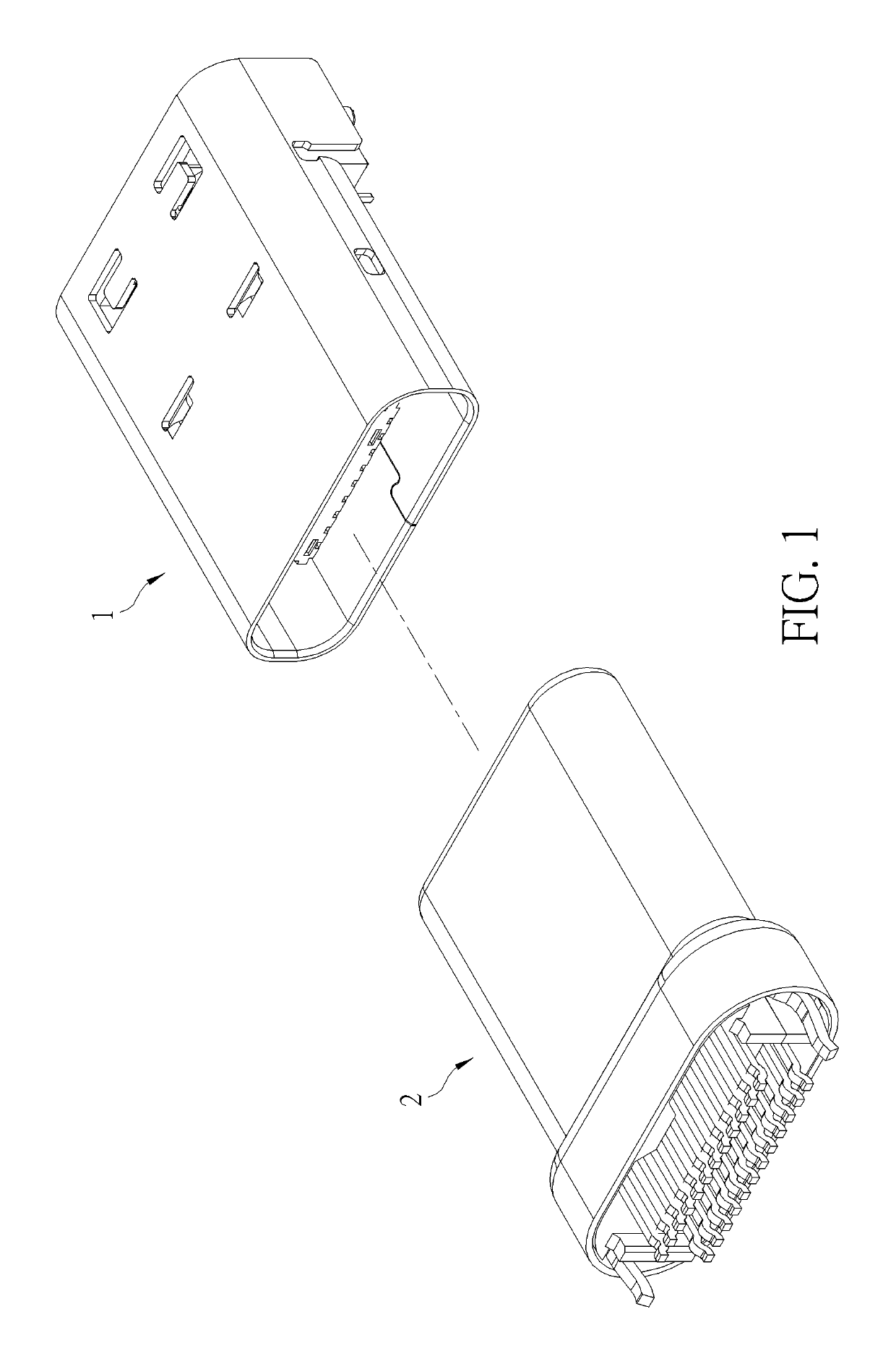
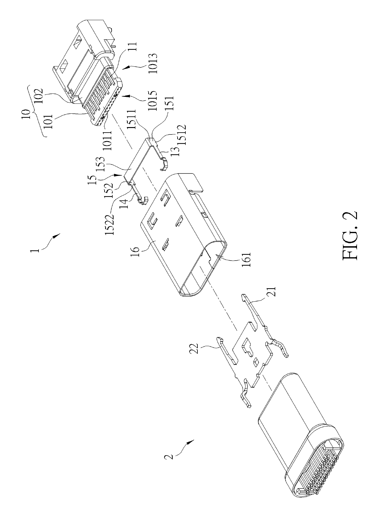
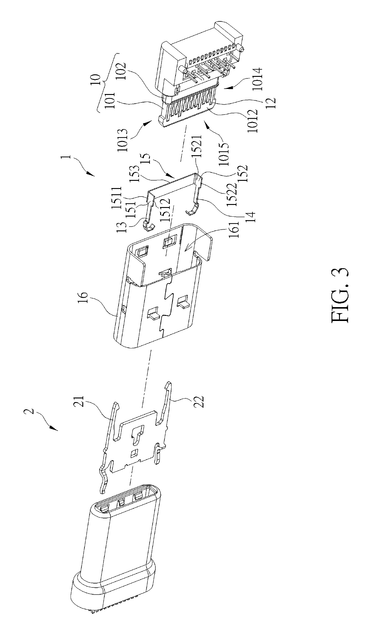
[0022]Please refer to FIG. 1 to FIG. 3. FIG. 1 is a schematic diagram of an electrical receptacle connector 1 and a corresponding electrical plug connector 2 according to a first embodiment of the present invention. FIG. 2 and FIG. 3 are exploded diagrams of the electrical ...


PUM


Abstract

An electrical receptacle connector includes an insulator, a first contact set, a second contact set, a U-shaped shielding structure, and a first plate member. The insulator includes a tongue and a base connected to the tongue. The first contact set and the second contact set are disposed inside the insulator and exposed out of a first side and a second side of the tongue opposite to each other. The U-shaped shielding structure is disposed on the base and at least partially exposed out of the base. The first plate member extends from an end portion of the U-shaped shielding structure along a third side adjacent to the first side and the second side of the tongue and toward a front end of the tongue. The first plate member includes a first step structure. Therefore, it effectively prevents the tongue from being worn or deformed by insertion and withdrawal forces.

Description

BACKGROUND OF THE INVENTION1. Field of the Invention[0001]The present invention relates to an electrical receptacle connector, and more particularly, to an electrical receptacle connector capable of preventing damage or deformation of a tongue.2. Description of the Prior Art[0002]An electrical connector is an inevitable component of an electronic device for battery charge or signal transmission of the electronic device. However, with frequent insertion and withdrawal of the electrical connector, a tongue of the electrical connector may be worn out to be damaged or even to be broken easily. An electrical receptacle connector is usually built into a main board of an electronic device. Therefore, if a tongue of the electrical receptacle connector is damaged or broken, it is required to repair or replace the main board of the electronic device, which leads to high maintenance cost.SUMMARY OF THE INVENTION[0003]Therefore, it is an objective of the present invention to provide an electric...

Claims


Application Information

Patent Timeline
Patent Type & Authority Patents(United States)
IPC IPC(8): H01R13/6581H01R13/6594H01R12/71H01R24/60H01R107/00
CPCH01R13/6581H01R13/6594H01R2107/00H01R24/60H01R12/716
Inventor CHU, YU-CHING
Owner VITECK
Why Eureka
Try Eureka