Supercharge Your Innovation With Domain-Expert AI Agents!

System and method for well lifecycle planning visualization

a lifecycle planning and visualization technology, applied in forecasting, instruments, data processing applications, etc., can solve the problems of single solution to a complex problem that is often not very useful, not contemplated, and the impact of instant inventors on the production of hydrocarbons, so as to improve the contribution of instant inventors to the ar

Active Publication Date: 2019-09-24
BAKER HUGHES ESP INC
View PDF47 Cites 0 Cited by
  • Summary
  • Abstract
  • Description
  • Claims
  • Application Information

AI Technical Summary

Benefits of technology

This patent describes a system and method for creating a well lifecycle plan that includes multiple types of lifts and their configurations. The system includes a three-level visualization system for reviewing the different lift options. The plan includes performance models and financial information. The technical effects of this invention include the ability to predict when or if a lift plan will need to be changed in the future and the ability to explore variations on the chosen option within practical limitations. The invention is not limited to the described details and can be used in different ways.

Problems solved by technology

Determining the most suitable type of artificial left to employ in a hydrocarbon producing well is a complex decision that involves a number of different factors including, for example, technical feasibility, lift parameters, operating costs, maintenance practices, reliability, target productions, engineering design, company preferences and other factors.
Of course, fluid production from a hydrocarbon well is a dynamic quantity and the lift technology that is appropriate today might not be appropriate in the future.
A key challenge is displaying the wide variety of options to the user in a way that facilitates decision making.
Even in circumstances where a well lifecycle plan is determined algorithmically, a single solution to a complex problem is often not very useful since real world considerations sometimes prevent an operator from following the plan exactly.
As a result, even an optimum process incorporates a limited view of what might be the most suitable overall solution.
Further, it might not contemplate if or when a future change in the well's decline curve would call for replacing the current lift type with one that more suitable to the then-current production level.

Method used


Image

  • System and method for well lifecycle planning visualization
  • System and method for well lifecycle planning visualization
  • System and method for well lifecycle planning visualization

Examples


Embodiment Construction

[0027]While this invention is susceptible of embodiment in many different forms, there is shown in the drawings, and will herein be described hereinafter in detail, some specific embodiments of the instant invention. It should be understood, however, that the present disclosure is to be considered an exemplification of the principles of the invention and is not intended to limit the invention to the specific embodiments or algorithms so described.

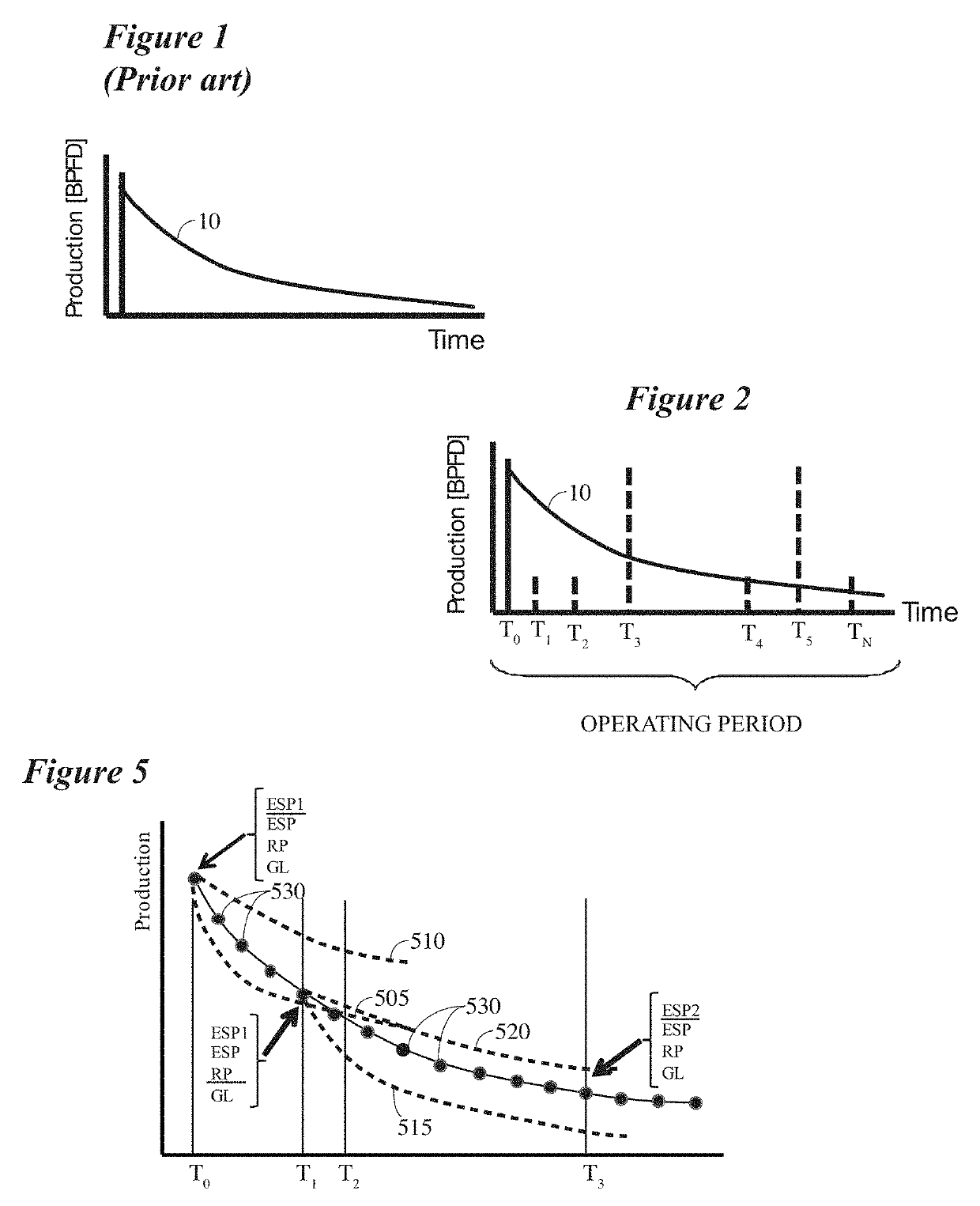
[0028]Turning first to FIG. 1 which contains an example of a prior art well decline curve, it is well known in the reservoir engineering field to calculate a decline curve for a particular well. There are numerous acceptable methods of doing this including, for example, Arps algorithm, hyperbolic decline, exponential decline, harmonic decline, etc. FIG. 1 contains a schematic representation of a decline curve which illustrates production rate versus time for a hypothetical well, where “BPFD” on the “Y” axis represents “barrels of fluid per ...


PUM


Abstract

According to one embodiment, there is provided herein a system and method for producing a well lifecycle lift plan that includes considerations of multiple types of lift, multiple lift configurations associated with each lift type, and can be used to provide a prediction of when or if it would be desirable to change the lift plan at some time in the future. Another embodiment utilizes a heuristic database with rules that might be used to limit the solution space in some instances by restricting the solution to feasible configurations. A further embodiment teaches how multiple individual well optimization results might be combined with a reservoir model to obtain an optimized lift schedule for an entire field.

Description

CROSS REFERENCE TO RELATED APPLICATIONS[0001]This application claims the benefit of U.S. Provisional Patent Application Ser. No. 62 / 344,562, filed Jun. 2, 2016, titled “WELL LIFECYCLE PLANNING VISUALIZATION ELEMENT,” the entire disclosure of which is incorporated herein by reference as if fully set out at this point.TECHNICAL FIELD[0002]This disclosure relates generally to production of hydrocarbons and, in more particular, systems and methods for optimizing and visualizing hydrocarbon production from a well over time.BACKGROUND[0003]Determining the most suitable type of artificial left to employ in a hydrocarbon producing well is a complex decision that involves a number of different factors including, for example, technical feasibility, lift parameters, operating costs, maintenance practices, reliability, target productions, engineering design, company preferences and other factors. Choosing a lift type is often made based on what has been done in the past and an individual's expe...

Claims


Application Information

Patent Timeline
Patent Type & Authority Patents(United States)
IPC IPC(8): G06Q10/06G06Q50/06G06Q10/04
CPCG06Q50/06G06Q10/04G06Q10/0637
Inventor RASHEED, ADAMVAN DAM, JEREMY DANIEL
Owner BAKER HUGHES ESP INC
Features
  • R&D
  • Intellectual Property
  • Life Sciences
  • Materials
  • Tech Scout
  • Unparalleled Data Quality
  • Higher Quality Content
  • 60% Fewer Hallucinations
Learn More